Equinor reaping benefits of wired drill pipe, lab trials for Barents Sea injectors
Norway’s offshore operators were strongly represented at the SPE/IADC Virtual International Drilling Conference earlier this year. Among those submitting multiple presentations were Equinor, with updates on technical developments at various fields on the Norwegian continental shelf that have continued throughout the pandemic.
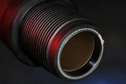
Børge Nygård, Lead Advisor, Drilling Technology at Equinor, related some of the improvements to the company’s drilling operations since the introduction in 2017 of wired drill pipe (WDP) and along-string measurement (ASMs), a co-development with NOV. The WDP extends from the surface through to the bottomhole assembly (BHA), with measurements taken regularly along the string and at the BHA, such as temperature, pressure, vibration, torque, tension, and bending moments.
The ASM tools are typically placed in the open-hole: the signals require electrical power to travel up and down the pipe, so repeater subs with batteries are also placed at 300-m (984-ft) intervals along the drillstring. The bi-directional telemetry provides 56 kbits/s and is independent of flow. On reaching the surface, the data travels underneath the top drive, through cables and down to the drill floor where it is distributed through a controller unit to different users of the telemetry. Surface, network and computer systems at various positions on the rig and in the driller’s cabin allow multiple personnel to visualize the WDP data.
Another feature of the process is a data while tripping (DWT) device, a remotely-operated retractable system mounted on the base of the top drive. This enables a connection to the WDP when the pipe is held by the elevators and not screwed into the top drive, during tripping. The DWT is engaged from the driller’s panel by a yellow arm sliding down into the box, creating a connection, but this is only done when there is sufficient weight hanging in the elevators. Benefits include improved safety, with fewer personnel needed on the rig floor when testing the WDP, and reduced testing time. In addition, the DWT provides options for collecting information from the BHA and the along-string sensors while tripping.
Equinor has used WDP extensively in the North Sea, and on five different rigs to drill in total more than 130,000 m (426,508 ft) and over 160 well sections, in hole sizes from 26-in. to 8½-in. On one rig it has helped to more than double average net ROP, from 35 m/hr to 75 m/hr (115 ft to 246 ft), with telemetry savings on the same rig of around 200 hr during 16 months of operations. The company has also used WDP to retrieve an 81-m (266-ft) core in one run from a floating rig in the Barents Sea, and to potentially save difficult sections from technical side tracks.
To get the most out of WDP, however, the operations team must get into the habit of taking decisions based on the new data, Nygård cautioned, rather than fall back on established drilling practice, and do so while drilling and monitoring the effects in real time. When implementing WDP, he added, it is important to identify all required components early to ensure compatibility with planned operations. And the operator, drilling contractor, drilling service company, and WDP provider must all be continuously involved in a One Team Approach.
At the same time, not everything is plain sailing. Equinor has encountered issues with the inductive couplers installed in the connections, which can cause the WDP to function only as a conventional pipe. But this type of situation can also be forestalled through ensuring a strong focus on handling by all personnel involved both prior to and during operation, with frequent testing performed on connections to mitigate such issues. The DWT is useful in allowing faulty connections to be identified early.
As for the gains, for one large, phased North Sea drilling campaign, Equinor drilled three wells in the first phase using conventional pipe, and the nine that followed in Phase 2 with WDP. The second phase wells achieved increased section length and significantly higher rate of penetration (ROP) in all the 17½-in., 7¼-in. and reservoir sections. However, the ROP gains were not down to WDP alone, but also other actions on the rig, and a general effort to improve drilling efficiency. In addition, the ASM tools made it possible to continuously evaluate the downhole conditions. The pressure along the string determined if the hole was being cleaned while drilling or if ROP needed to be reduced.
For the Phase 1 wells the average time spent circulating hole clean-out at section TD was 10.3 hr, while for seven of the Phase 2 WDP wells, on average 6.5 hr was saved on this operation alone, i.e. a 63% reduction in circulation times to TD. And the 12¼-in., sections were around 23% longer in Phase 2.
So how does WDP increase efficiency? Equinor employs ASM tools to deliver an increased volume of data: visualization needs to be put in place widely to allow for fast and easy interpretation so that individuals can decide on appropriate operational changes where needed, via a system that combines time, depth and real-time measurements. As an example, for the phase drilling campaign seawater and pills were used to clean the hole, while at the same time, the team sought to increase ROP. Color coding was used to show changes in hole cleaning during this process, until the time came to reduce ROP and regain hole cleaning. As for shortening circulation time, this decision was based on actual downhole data instead of standard hole cleaning practices, with a range of colors used to show that the hole section was already clean 1½ hr earlier.
Equinor has also used WDP data to assess drillstring vibration mitigation when drilling challenging hole sections, with favorable results. Further benefits could be expected when applying the telemetry to improve well placement, Nygård concluded.
Well integrity management
Claas van der Zwaag, Lead Engineer, Drilling and Well Operations at Equinor, spoke of how the repercussions of the P-31 A well blowout on the Snorre A TLP in late November 2004 are still influencing the company’s well integrity management today. Saga Petroleum, the original developer of the Snorre field, first drilled the well in 1995. While cementing in the reservoir section, the drillstring became stuck in cement, necessitating a long fishing/milling operation. This caused extensive wear and holes in the 9⅝-in. production casing: Saga opted to install a scab liner on the inside of the casing to cover the holes and areas of wear, but production was not as expected, so the well was converted to a water-alternating-gas injector.
After taking over as operator, Statoil (now Equinor) decided to perform a wireline operation in late 2003 to qualify the well for a recompletion. A plug was installed in the tail pipe below the production packer, but the A-annulus did not pass a leak test, with indications that the well could leak through the scab liner and holes in the casing. When the well was deemed unfit for requalification, a new plan was put together to P&A and side track to recover the well slot. But when the Snorre A rig skidded onto the slot in November 2004 to start the operation, changes to the plan – one being to squeeze cement – had not been processed properly. Statoil chose to perforate the tail pipe beneath the production packer in order to secure access to the reservoir for performing the cement squeeze. But this meant the scab liner and holes in the casing were no longer mechanically isolated from the reservoir while pulling the tubing and scab liner.
On Nov. 28, when operations were under way, there were indications of swabbing and unstable well conditions. All the mud was bullheaded to stabilize the well, while the rig crew continued to pull the scab liner. When the top of the liner was in the rotary table, a well control situation arose, leading to shut-in of the well on the annular preventer; overnight, the crew encountered difficulties stripping back the liner to the hole, and gas escape was then reported both beneath and on the platform, triggering an emergency shutdown of the rig. Containing the incident became a struggle when the rig crew ran out of mud, although they were eventually able to mix sufficient water-based mud mixed with chemicals to plug the leak from the well to the seafloor and kill the well.
Statoil was hit with a fine and censured for inadequate risk assessment and management involvement and for failing to comply with well barrier requirements. According to van der Zwaag, the incident served to amplify attentiveness to well integrity in the industry and formed the basis for key measures that are in use today. In Equinor’s case, this includes connecting highest-level HSE via Norway’s NORSOK D-010 industry standard for well integrity in drilling and well operations to the company’s well integrity management principles. Complementing NORSOK D-010 are the NOROG 117 guidelines issued by the Norwegian Oil and Gas Association, which define the essential elements of well integrity and management systems, such as well integrity training, well handover documentation, use of well barrier schematics in the operational phase, and a well integrity categorization system.
The two most important organizational changes at Equinor following the incident were the establishment of a) a subsurface support center for drilling and well operations, supporting assets across the company with the latest best practice; and b) a well integrity management organization. At the same time, the company’s management system transitioned from a library-based steering system to today’s workflow-based steering system. This includes clearly defined work processes related to well integrity management, and roles and responsibilities for various tasks throughout the well’s lifecycle.
After Snorre A, Equinor developed a substantial professional workforce within the well integrity discipline with job positions created for what today is known as well integrity engineering, van der Zwaag said. The company has also established various competence management activities since 2004, with attendance at an annual two-day well integrity seminar mandatory for all drilling and well personnel in operations positions. And offshore/onshore staff working with wells handed over from Drilling & Well to Production Operations must attend well integrity courses and seminars every five years.
Johan Castberg injection studies
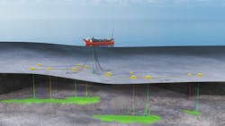
Charlotte Eliasson, Principal Engineer Well Operations Completions at Equinor, recounted the reservoir drilling and breaker fluids qualification process for direct injection wells on the Johan Castberg project in the Barents Sea, based on a paper co-presented with Halliburton. This is a large subsea development taking in the Skrugard, Havis and Drivis structures, all featuring shallow reservoirs with hydrostatic pressure and low temperatures. The field is being developed via a combination of long horizontal producer wells, single and multilateral; horizontal gas injectors for pressure support and gas disposal; and deviated water injectors for pressure support and accelerated production.
Equinor identified injectivity of the water injectors as one of the development’s top 10 risks. Water will be injected under matrix conditions, cooling the formations and creating fractures that will propagate over time, securing high injection rates over the lifetime of the wells. But injection pressures that are too high could cause out-of-zone injection, with the fracture growing outside the reservoir zone and potentially spreading through the overburden right up to the seabed. To contain fractures within the reservoir, injection pressures must be maintained below the minimum horizontal stress of the overburden.
Johan Castberg’s combination of shallow reservoirs and low pressures means that the water injectors cannot be cleaned prior to initiating water injection, hence the need for direct injection wells. The reservoir completion and fluid design are both vital to secure injectivity. For the fluid qualification, Equinor assembled a multi-disciplinary team of drilling fluids, production technology and completions specialists, working with chemists at fluid laboratories to qualify the drilling and completion fluids. The main considerations for this type of program, Eliasson noted, are whether the fluids should be water or oil-based; the type of bridging material; the concentration of polymer; and the compatibility with the reservoir fluid to avoid emulsion and precipitation occurring. For the completion fluids, the plan was to run the lower completion via screen-driven fluid, displace for brine, and place a breaker. But how should the breaker be placed in the reservoirs, and how should the configuration be set up to ensure operational success?
The team identified a wish-list for securing injectivity. These included a water-based drilling fluid, to ensure compatibility with the reservoir fluid; use of sized salt as a bridging material that would be soluble in the injection water; deployment of an acid pre-cursor in the breaker formulation; and keeping the concentration of polymer low. Other aims were breakthrough times (contact with the reservoir) of less than 2 hr, and to leave no residues that might at some point impact the injectivity of the water injectors. As for the breaker fluid design, it was important for the fluid to develop a formic acid when mixed with water and exposed to the reservoir temperatures.
Equinor decided to use new mud for each well to avoid contamination of the filter cake and drilling materials while drilling several water injectors back-to-back. The team also sought to verify the interaction between the breaker and filter cake; check the breaker’s chemical capabilities with the filter cake; and to verify the minimum possible interaction with reservoir fluids. For the completion design, a priority was to ensure and even and effective breaker placement along the entire injection interval. Johan Castberg’s wells will have open-hole completions, with pre-drilled liner in the reservoir sections. By using a simplified gravel pack system, with a gravel pack port and a wash pipe, the breaker can be placed throughout the injection interval before being activated, with the entire filter cake exposed to the breaker fluid.
The wash pipe is run on the inside of the pre-drilled liner through to the toe of the well. The breaker fluid is circulated down the wash pipe, out into the reservoir annulus and up the full reservoir section. After pulling out the wash pipe the entire reservoir is filled with breaker fluid: during the pulling procedure, the wash pipe is placed directly under the reservoir barrier valve, and once losses are confirmed, it is completely pulled out and the barrier valve is closed. By being able to confirm losses while at the same time retaining well control, “the set-up allows us to go down with the wash pipe again to the toe of the well and create new, fresh breaker fluid if needed,” Eliasson explained.
The test campaign at Halliburton’s fluid laboratory in Tananger started with standard qualification which was used for the further breaker qualification. Checks were performed of rheology, sag, mobility and fluid loss. “It was an iterative process, during which we observed starch and polymer concentrations, both important for success. We revisited the formulations many time and optimized the results to deliver a fit for purpose drilling fluid.”
For the rheology, the set-up replicated seabed conditions at 4°C (39°F) and flowline conditions at 20°C (68°F). Fluid losses increased with temperature and decreased with the addition of HPC, a clay material, to simulate drilling materials. Results were as expected, and also corresponded with experiences at the field. For the filter cake solubility, a chemical suitability test was performed to verify that the breaker worked on the filter cake – the latter was created on a ceramic dish, then lifted off and placed in a breaker solution at reservoir temperature for five days. Two different temperatures were applied – one at 44°C (111°F) to simulate conditions at Skrugard, another at 71°C (160°F) representing Havis. The filter cakes dissolved completely in both tests after five days, indicating that no residuals will be left in the reservoir that might plug it and reduce injectivity.
The breakthrough test was designed to provide the time taken for the breaker fluid to break through and penetrate the filter cake and establish contact with the reservoir. Dissolving of the polymer in the filter cake left a lunar-type surface, which showed that breakthrough had been achieved and that the reservoir would be accessed. At higher temperatures the process proved to be faster, the breakthrough time of 71°C being 1.25 hr compared with 2.7 hr at 44°C. Although the latter was longer than the 2 hr targeted, it was still seen as acceptable.
The test results, Eliasson concluded, showed that the reservoir drilling fluid has been optimized to create a filter cake that can be easily removed using the breaker fluid. The completion design and operational procedures have been customized and optimized to ensure maximum reservoir exposure of the breaker fluid system. Development drilling started on the field last August: for the first water injectors there have been indications of losses, which means that the fluid and breaker systems do work. Actual injection is due to start in 2023 when the FPSO is in place.
References: SPE/IADC Virtual Drilling Conference, March 2021
The Snorre A 2004 Blowout and Its Impact on Drilling and Well Operations Today C.H. van der Zwaag, T. Paulsen, Equinor ASA
Reservoir Drilling, Completion and Breaker Fluid Qualification for Direct Injection Wells on the Johan Castberg Field - A Multi-disciplinary Study to Secure Injectivity C. Eliasson, O. Braadland, H. Kaarigstad, A.M. Mathisen, Z. Ibragimova, Equinor ASA; B. Salmelid, Halliburton
Improved Drilling Operations with Wired Drill Pipe and Along-string Measurements - Learnings and Highlights from Multiple North Sea Deployments B. E. Nygård, E. Andreassen, J.A. Carlsen, G.Å. Ulfsnes, S. Øksenvåg, R. Stabell, T. Davis, Equinor; T.L. Naterstad, S. Zainoune, E. Vandvik, NOV
About the Author

Jeremy Beckman
Editor, Europe
Jeremy Beckman has been Editor Europe, Offshore since 1992. Prior to joining Offshore he was a freelance journalist for eight years, working for a variety of electronics, computing and scientific journals in the UK. He regularly writes news columns on trends and events both in the NW Europe offshore region and globally. He also writes features on developments and technology in exploration and production.