New generation TLPs for West Africa
Willie Rawles, MODEC
Dr. Pieter Wybro, WorleyParsons Sea
Tension leg platform (TLP) design drivers for West Africa are both similar and different to those areas where TLPs have been a platform choice for many years.
The differences include requirements such as platform drilling, inshore topsides integration, soils conditions not normally encountered in other deepwater locations, swell conditions that affect not only in-place performance but also installation, the lack of pipeline to shore infrastructure, and the limited near-shore support facilities. Other platform drivers can be satisfied with equipment and resources generally available in West Africa, such as drilling tenders and mobilized heavy lift equipment.
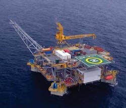
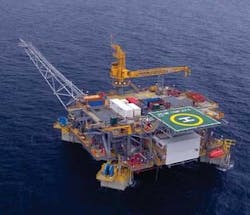
New generation TLPs were installed in the Oveng and Okume/Ebano fields in Equatorial Guinea for Hess Corp. and its partners.
As operator, Hess awarded an engineering, procurement, and construction (EPC) contract to MODEC for the two TLPs for the Oveng and the Okume/Ebano fields in 900 ft (274 m) and 1,650 ft (503 m) water depth, respectively. This was a fasttrack project and the TLPs were constructed ready-for-sailaway in just over 16 months from contract award.
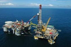
The operating strategy was to use a semisubmersible drilling tender coupled to the TLP during drilling and completion activities with the second TLP in a stand-alone operating condition.
With similar payload, operating, and functional requirements, along with the same required delivery date, this strategy made it attractive to design nearly identical platforms.
West Africa versus US Gulf of Mexico TLPs
Certain TLP design drivers for West Africa are quite different than that for the US Gulf of Mexico. Typical design drivers for all West Africa TLPs to date include:
- Mild environment with squall and persistent swell conditions which affect in-place performance and installation
- Full platform drilling
- Inshore topsides integration
- Minimal processing on the TLP (final processing is done on an FPSO or other facility)
- Unusual soils conditions.
To gain perspective of the differences between current West Africa TLP designs, a comparison of the steel weight efficiency metrics for the two types of TLPs and the GoM TLPs are shown on the next page.
Industry firsts
The Oveng and Okume TLPs achieved several industry firsts for TLPs, including:
- First use of a MOSES SSIP TLP with the topsides integrated at the fabrication quayside
- First use of tender-assisted drilling in West Africa environment
- First time two TLPs, identical in nearly all respects except for water depth and test separation, were fabricated in parallel
- First time two TLPs were transported on one heavy lift transport vessel
- First time two TLPs were installed sequentially in one mobilization of a construction spread.
Design philosophy
Due to the remote location of the Oveng/Okume TLPs, it was anticipated that it might be expensive to use previous TLP installation strategies that included the mobilization of a crane vessel for installation of the topside. This was one factor that led to use of the new generation MOSES SSIP TLP, where the topside can be integrated at the fabrication quayside. The MOSES SSIP design has enough stability with the topsides integrated to allow installation without using the hook load of a crane vessel or temporary buoyancy. The installation stability was achieved by pushing the columns outboard of classic MOSES TLP columns and reducing the draft of the TLP. The draft and column spacing were carefully selected to provide enough stability for installation while avoiding any major impact on deck structure design or TLP dynamic response.
The MOSES SSIP TLP is a MODEC proprietary fifth-generation TLP design that offers in-situ safety and performance, design flexibility, fabrication simplicity, ease of installation, as well as reduced risk during installation. The novel hull form provides the superior efficiency, constructability, and hydrodynamic performance typical of a new generation TLP while having the stability necessary for quayside integration, eliminating the risk and cost of offshore topsides integration in the West Africa swell environment. The Oveng and Okume TLPs were the first applications of the new generation MOSES SSIP TLP.
The hull design philosophy was:
- To maximize the use of stiffened flat plate primary hull structure with simple connections for structural efficiency and constructability
- To radially orient the four rectangular columns for improved waterplane stability and improved deck structural support, thereby reducing deck spans and cantilevers, which reduced the size of the deck girders
- To give a unitized pontoon base structure
- To have four outrigger tendon support structures (TSSs) to increase the tendon support footprint, thereby reducing the tendon loads
- To provide open-end well bays to enhance platform safety and provide an arrangement for improved flexibility
- To reduce hull motions so that the top-tensioned production risers can be directly fixed to the deck without using conventional tensioners.
The design uses an open-end well bay which provides a number of safety and operational advantages as compared to a central well bay. These advantages include:
- Maximum separation between the wells and quarters to maximize personnel safety
- Maximum platform safety in case of a blowout or fire in the well bay enabling expulsion of gases and flames and open side access for firefighting
- Easy access to all dry trees and facilitates layout of jumpers, manifolds, and equipment, unlike designs with a central moonpool
- An unobstructed deck on the well bay side(s) for safer and easy rig-up of the drilling rig system
- Accommodate more TTR slots without major rework of the hull configuration.
The use of a tender rig for drilling reduces the drilling payload by approximately 75% compared to a self-contained platform rig of equal capacity. This allows the TLP to be smaller, equating to less weight and ultimately less expensive, without sacrificing drilling efficiency. This is due to the drilling tender’s ability to operate during all the same conditions that the self-contained rig can operate in the West Africa.
The design-one-build-two philosophy began at the sizing stage. The payload requirements of the two platforms were compared and it was determined that one size TLP hull could support the payloads of each TLP, even though the payloads and water depths were different. Two identical hull and deck structures were designed for the platforms. The hull structures for these two TLPs became the same. However, there are some differences for the topsides supports for equipments that had to be accounted for, but the primary structures are the same.
Performance versus stability
The enhanced stability of the MOSES SSIP versus a classic MOSES TLP is achieved by reducing the draft, by increasing column size, and by locating the columns further outboard on the tendon support structures.
The draft reduction increases the platform motions and tendon dynamic loads, and the column size and location primarily affects the deck design. The column size and spacing will affect the pry-squeeze loads from the hull to the deck, and the column located more outboard will increase the deck span, all of which contributes to a heavier deck. By careful balance of these effects, adequate stability can be achieved at the expense of only moderate decrease in performance that is acceptable to the riser design, and moderate deck steel weight increase.
Fully coupled time domain global performance analyses were performed for the stand-alone TLP as well as the TLP/TAD system.
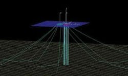
In the fully coupled analysis model of the TLP, the tendons and risers were modeled with large displacement beam elements. The movement of tendons and risers were solved together with the motion of the TLP. This global performance analysis methodology is important because of the large number of risers and relatively small size of the TLP.
The first order wave forces on the TLP were calculated in WAMIT in the frequency domain and transformed into the time series of wave exciting forces. Frequency domain added mass and damping were also transformed into time series using the retardation function. In addition to first order wave forces, seconds order sum and difference frequency wave forces were also calculated in WAMIT and transformed into time series of wave exciting forces. This ensures the capture of higher order response of the TLP.
The MOSES SSIP TLP hull consists of the base structure, CSS structure (connection between base and column), tendon support structure (TSS), node structure (intersection of column to TSS and CSS), column structure and column-to-deck connections. The base structure uses the same MOSES octagonal shaped closed girder structure at the center and provides a large part of the hull buoyancy. The base structure is connected to the four columns through four CSS structures. There are four TSS structures, each supporting two tendons. These four TSS structures are 90 degrees apart.
Tender-assisted drilling
Tender-assisted drilling (TAD) was selected to be the most economic option for this project. In the TAD approach, the drilling capabilities are provided by a drilling tender vessel (DTV), which installs and removes the drilling equipment set (DES) onto and from the TLP, while all other drilling related equipment, crew, power supply, drilling fluids storage and handling and related services are located on the DTV. The DES has to be lifted on and off the TLP in multiple lifts while the DTV is moored in close proximity to the TLP. This operation is performed during good weather conditions. During drilling operations, the DTV is moored at a much larger distance from the TLP, such that adequate minimum clearance is maintained between the DTV and TLP in the maximum drilling and one mooring line broken conditions.
Based on WorleyParsons Sea experience with the Chevron West-Seno TLP, where the DTV (the Seadrill West Alliance) was moored to the TLP using a coupled mooring system, a similar coupled system was selected for these West Africa TLPs. Extensive analysis of coupled and non-coupled systems show that in the coupled systems, the TLP and DTV slow drift motions tend to occur in unison, thus providing a relative constant distance between the vessels, while eliminating the need for regular spread mooring line adjustments which may be required for non-coupled systems. The coupled TAD mooring system also has the distinct advantage that the position of the TLP can be adjusted to align with wells, by manipulating all TAD spread mooring legs.
In the Oveng and Okume coupled TAD mooring systems, the DTV is moored on location by six spread mooring legs; four away from the TLP and two breast lines on the TLP end of the DTV.
The DTV is also moored to the TLP by a system of primary nylon hawsers and secondary nylon back-up hawsers. The TLP is equipped with two spread mooring legs opposite the DTV, which counter the mean hawser tensions, and are called the TLP holdback legs. The primary nylon hawsers have sufficient mean operating tension to minimize snatch loading. The mean operating tensions in these hawsers are created by the opposing restoring forces in the DTV legs and TLP holdback legs.
Metocean considerations
In the West Africa environment, the conditions governing the design of the TAD moorings are the persistent swells from the southwest and the sudden and potentially violent squalls. Although the environment is generally benign, the swells may generate high relative motions between the DTV and TLP requiring large elasticity in the coupling hawsers, while the sudden and unpredictable squalls induce substantial loads and the moorings and coupling hawsers. Since the strength of squalls are quite unpredictable, it is assumed that the DTV cannot be pulled away from the TLP in a timely manner, nor can drilling operations be fully halted to allow the DTV to pull away.
The detailed coupled TAD mooring system design was governed by the following requirements with the corresponding specific solution developed to meet these requirements:
Factors of safety for 100-year conditions comply with API RP 2SK, API RP 2M, and DNV-OS-E301 Position Mooring. These include:
- Minimum TLP/DTV clearances in 10-year conditions comply with the same codes, which require at least 10-m (33-ft) clearance in intact and one line damaged conditions. In 100-year one line damaged conditions, a small reduction of the 10-m (33-ft) clearance was allowed.
- The TLP and DTV centerlines were aligned with the predominant swells from the southwest such to minimize the DTV motions.
- Each TLP is equipped with a complete hawser system to allow the DTV to move between the TLPs, without the need to move the hawsers.
- The secondary hawsers function is to take over for a broken/failed primary hawser and are made strong and long enough to accomplish this.
- It was decided to use catenary preset spread mooring lines for the six DTV mooring legs. The primary reasons are that pre-installation allows accurate placement of the anchors and test loading of the anchors to maximum dynamic intact loads. Thus the integrity of the anchoring system is ensured by eliminating any DTV movement due to anchor drag.
- The TLP holdback legs are preset catenary mooring lines that attach to mooring wires deployed from wire rope winches that are deployed through underwater fairleads on the TLP columns opposite the DTV. These preset lines are test loaded also during pre-installation to ensure anchor holding.
- Both Oveng and Okume TLPs have their own preset spread mooring lines, which allow the DTV to disconnect and move between the TLPs without the need for anchor recovery and re-installation. There is a relatively deep trench within the anchor radius of the Okume/Ebano location and it was decided to move one of the anchors to the opposite side of this trench.
- In a coupled TAD mooring design it is important the stiffness of this system is comparable to the stiffness of the TLP tendon moorings and stiffness contributed by top tensioned risers.
- Analytically, these coupled systems are challenging and require analysis using fully coupled time domain simulations of all critical environmental conditions, intact cases, damaged cases, and transient conditions. Engineers used a customized version of WINPOST to perform these simulations, using complex models which incorporate both vessels all mooring lines, TLP tendons, TLP risers, and the coupling hawser systems.
- Compared to the previous proven TLP TAD mooring design complications, the Oveng/Okume designs have the additional squall conditions complication which had to be analyzed as transient conditions using three-second wind speed versus time record of squalls.
- One-line failures were also simulated during the squall simulation to account for the transient motions of the vessels due to a line or hawser breaking.
- The squall environment, with its rather strong gust wind speeds, ultimately governed the design of the system. Several iterations were needed to find the right combination of mooring pattern, line make-up, pretensions, hawser system design, and nominal vessel distance.
- The primary and back-up hawser systems required modifications and extra equipment on the DTV. On the DTV side, the back-up hawser are attached to the vessel bow mooring chains, while the primary hawsers are connected to chain led through additional column fairleads, with chain stoppers at deck level.
Moorings and foundations
West Africa soils are different from other areas, particularly the deepwater GoM. They generally do not produce high lateral stresses, which can be observed in the axial capacity, drivability, and set up.
The foundation for the TLPs was similar to previous MODEC TLPs using driven piles with tendon bottom connector receptacles located near the top of the piles (below the drive heads).
Analysis determined that the set-up time for the piles is longer in the West Africa soils than in typical GoM soils. This led up to different set-up criteria for the piles than usual due to the preferred installation sequence of the two TLPs instead of one, and the long set-up times. The installation sequence was two sets of piles installed at about the same time, then the tendons pre-installed, then the platforms attached right away. One TLP would begin drilling and completion operations for an extended period of time while the other TLP would not be operating with drilling or production risers for an extended length of time.
The tendon design is similar to previous MODEC designs. The tendon main body sections were designed to be interchangeable between the two TLPs which made fabrication, transportation, and installation less complicated since they did not need to be segregated. The tendon lengths were established with custom bottom section lengths for each corner of each TLP. The main body sections were kept short (240 ft [73 m]) to allow possible option of a smaller installation vessel. The tendon top and bottom segments were of different lengths (between the TLPs) to account for water depth and seabed slop.
Fabrication strategies
The Oveng and Okume/Ebano MOSES SSIP TLPs essentially were fabricated concurrently with only a minor variation in activity start dates. The design allowed the fabricator to use efficient fabrication techniques of building components for both platforms.
This strategy, however, comes with certain risks. The following are risks with corresponding mitigation strategies that were successfully used for theses new generation West Africa TLPs:
- The schedule did not allow for incorporating lessons learned from one platform to the next. This challenge was overcome through detailed planning and implementation of quality assurance measures during the design phase.
- Load out and integration at the fabrication quay. Through design and fabrication planning, these activities for both TLPs occurred flawlessly within 11 days.
- Pre-commissioning and commissioning activities run concurrently during the final months of fabrication. Again through proper planning and significant efforts by all team members, non-hydrocarbon systems on both TLPs were substantially commissioned prior to their departure from the fabrication facility.
- Loading and seafastening of both TLPs on one heavy-lift transport vessel. Again through proper planning, both TLPs were successfully loaded, seafastened, and safely transported from Asia to West Africa.


