Untested technologies encourage industry to invest in the future
Jay Schempf, Special Correspondent
While some novel tools and technologies revealed at the annual Deep Offshore Technology conference will never be used in the field, others are so pertinent, so logical, and so rational it seems like an understatement to deem them “inevitable.”
In an admittedly subjective appraisal of DOT technical papers dealing with inventive tools and innovative ideas that have so far not made it into the deepwater and ultra deepwater arenas, the editorial staff ofOffshore magazine has come up with a list of some ideas they think have a high probability for eventual development.
Compiled only from DOT conferences during the new century, including particularly innovations discussed in the 2004 conference in New Orleans and 2005 conference in Vitoria, Brazil, each of the following is considered byOffshore’s editors to be good bets to reach the deepwater subsea market - sooner or later.
Ultra-high strength casing for deepwater applications
At DOT 2004, Grant Prideco petroleum engineer Bruce E. Urband and BHP-Billiton engineer Dale Bradford observed that drilling extremely deep wells in water depths of 8,000 ft (2,400 m) or more puts significant strain on casing design, mainly due to the extreme burst, collapse, and tension loads required for casing at such depths.
For BHP’s Gulf of Mexico deepwater drilling operations, Grant Prideco provided 13 5/8 in. (346 mm) OD by 5/8 in. (16 mm) wall (86.86 #ft-plain end), TCA 150-Q1 grade casing, which was used successfully to drill a well to TD of 30,700 ft (9,210 m) in 8,831 ft (2,650 m) of water.
BHP had planned a deep target depth of 20,750 ft (9,225 m) for its Chinook-3 prospect in the GoM, and had determined that standard API Q125 casing would not meet burst design requirements unless it had a heavier wall thickness. For this well, however, the planned 13 5/8 in. (346 mm) casing seat was so deep that casing with heavier wall thickness was not acceptable because the casing load would exceed the rig’s hook load limit. Eventually, BHP elected to specify a high yield strength casing string that could meet the burst requirements at a minimized hook load.
The well presented design challenges that have become more common as the industry has pushed the envelope for exploration drilling into deeper wells in deeper water.
At that point, BHP realized meeting the burst design criteria was impossible with conventional 13 5/8-in. (346 mm) Q125 casing. Alternative sizes of Q125 were evaluated, but design weights exceeded the rig’s hook load capacity and would not accommodate the combined weight of the casing and land string plus an over-pull margin, which was limited to 1.5 million lb, the rig’s maximum hook load. Unlike some fifth generation ultra deepwater rigs, the one contracted by BHP had a top drive rated at 750 tons (680 metric tons) that could not be retracted from the load path while running casing. As a result, the company evaluated high-strength TCA150-grade casing material.
They concluded that numerous deepwater offshore operators - including BP, Anadarko, El Paso, ChevronTexaco, and others - had used TC140-Q1 and/or TCA150-Q1 casing products. As deepwater and high-pressure/high-temperature applications continue to stretch the limit of traditional casing grades such as P110 and Q125, greater consideration will be directed at the 140 and 150 grades, provided they are manufactured with the necessary processing controls to enhance fracture toughness. “The use of these grades will reduce string weights and hike economic incentives to drill and complete wells that previously were unattainable,” the authors noted.
New dry tree types for deepwater spars
Typically, buoyancy cans constitute the tensioning system for the top tensioned risers (TTR) used with dry tree wells aboard spars. But in their DOT 2004 technical presentation, “An Alternative Dry Tree System for Spar Application,” authors Alan Yu and Ming Leung, both of Technip, and Tim Allen of BP, noted that using hydraulic tensioners directly on the spar reduced its heave response and pitch motion.
As operator for Shell, BP elected to evaluate several top tensioning systems (TTS) for its Holstein field truss spar in Green Canyon blocks 644 and 645 in 4,344 ft (1,300 m) of water in the GoM 150 mi (241 km) south of New Orleans. The spar is a central facility to be equipped with dry trees and TTR. Initially, nine wells were to be drilled from the spar, with three more spare slots for later dry completions. A mobile rig was drilling satellite wells for subsea tie-ins to the spar.
The TTR concept the development team chose for Holstein was an individual tensioner spar supported vertical riser (SSVR) system.
A basic premise in the evaluation of the SSVR concept was to use as much available mature equipment as possible, including subsea tieback, stress joint, standard riser joints, keel joint, and tension joint for load transfer from the riser to the tensioning system.
For the SSVR system to function efficiently, an essential requirement was that the overall axial (i.e. heave) stiffness would be used to suppress the spar’s heave motion. Also, riser stiffness generated restoring force at the keel to reduce the spar’s pitch motion.
The Holstein dry tree outer risers and tensioning system were installed successfully and appeared to be running smoothly, the authors concluded. The true benefit of the system, they added, is the ease of access to the dry trees and the ease of tensioning system maintenance. What’s more, they said, an important advantage of the SSVR system is that it can be used to change out any existing tensioning equipment aboard existing spars, should that costly contingency arise.
Lemons to lemonade: Floating LNG system for stranded gas
Generally, there is little or no offshore production infrastructure in remote parts of the world for handling natural gas reserves associated with deepwater oil discoveries.
In their DOT 2004 presentation, “Development of a Floating LNG Facility for Stranded Offshore Gas,” authors Charles Borland, Masoud Deidehban, and Fredrik Savio, all of ABB Lummus Global’s floating production systems unit, said while giant oil fields off West and North Africa, the Middle East, and Southeast Asia justify large LNG facilities, offshore oil fields with typical peak production of up to 300,000 b/d with associated gas production of 250 MMcf/d do not.
As a possible solution to such a scenario, ABB Lummus developed a floating LNG facility that can be moored in deepwater next to a remote oil production facility. The floating LNG system, based on a proprietary ABB Lummus process, is viable for developing stranded gas in the 0.5-3.0 tcf range with production rates from 75 to 300 MMcf/d.
The ABB Lummus system is based on a patented turbo expander process that uses no intermediate liquids for cooling, leading to low equipment inventory and no requirement for cooling fluid storage. Typically, produced LNG is stored in a gas tanker with an on-deck LNG processing train. Gas streams then either can be preconditioned (NGLs and contaminants removed) or processed aboard a nearby floating LNG plant for offloading into shuttle tankers.
This “niche” LNG concept, the authors noted, is an economically viable solution for stranded gas.
The idea of turning such resources into a commodity should appeal to both host countries and the operators of producing properties, they added, since many stranded gas resources are not currently being utilized fully in some parts of the world.
Feasibility studies show that floating LNG plants and their associated LNG transport fleets can deliver product to markets economically despite the added costs associated with receiving the stranded gas from a deepwater field, processing it into products like LNG, and then offloading and transporting it to re-gasification facilities for direct sale.
Ring spar jabs away at production costs
With three generations of spar technology behind them, the designers and fabricators of floating production systems have not stopped innovating. In fact, a veteran offshore engineering/construction contractor used DOT 2005 to introduce a new, fourth spar hull configuration.
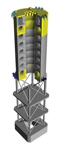
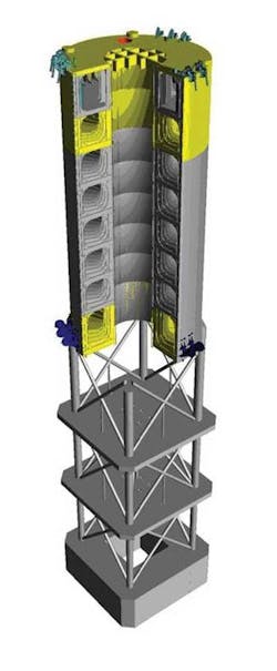
In his paper, “Fourth Generation Spar Technology,” J. Ray McDermott Inc.’s Rick Johnson showcased the company’s ring spar, which is similar to a truss spar, but with an alternative hull configuration and structural changes to the hard tank section which combine to reduce fabrication costs.
The design focuses on improved structural efficiency and ease of construction. This improves overall project cost and scheduling while addressing safety issues around compartment confinement, above-ground working areas, ease of inspection, and increased in-shop fabrication. Standardizing hull components opens doors to subcontracting components and increasing competitiveness.
The new structural system allows far more hull work to be completed under cover and, therefore, to have longer full crane access during fabrication. Also, it provides weight reduction in the hard tank section. Particularly dramatic are the gains in yard productivity afforded by the structural system, compared to that generated by traditional stiffened plate spar hull configurations.
The ring spar hull is significantly more cost competitive with semisubmersible and TLP-type floating production structures than previous spar types, the author said. Through new techniques and “outside of the box” thinking, the ring spar is a lighter, more construction-friendly hull. When optimized, these techniques result in lower cost and improved fabrication scheduling.
Returning to yesteryear: Pipeline towing for deepwater
In their DOT 2005 presentation, Vincent Alliot, Haiyan Zhang, and Erik Christiani of Stolt Offshore (now Acergy) said that the traditional approach to deepwater pipeline projects has been to upgrade existing spreads or to design new ones to meet pipelay requirements. While this works well in the GoM and West Africa, for example, developments in remote areas can be difficult for efficient use of pipelay assets due to unfavorable economics associated with moving those large vessels into deeper and deeper water around the world.
The three titled their technical paper “Pipeline Towing Methods for Ultra-Deepwater Conditions - Lessons Learned from the Past Used to Achieve the Requirements of the Future.” The paper analyzed the suitability of pipeline towing techniques, which were developed during the early 20th century to transport pre-built pipelines from shore to oil and gas developments in shallow bays and inland lakes along the Gulf Coast. It also draws on the concept of towing pipelines in ultra deepwater such as the detailed preparations made in the 1960s to install a gas pipeline across the Mediterranean Sea between Algeria and Spain.
Stolt Offshore used data collected from a full-scale towing test conducted in those early days in 8,200 ft (2,500 m) of water to validate the proposed Algeria-to-Spain line, combining them with modern technology and lessons learned from deepwater operations in West Africa to reassess the viability of towing pre-built lines under ultra deepwater conditions.
Successful towing of bundled risers and production flow lines from shore to the Girassol project offshore Angola motivated Stolt Offshore engineers to consider that method for developing deepwater oil and gas fields. Engineering work resulted in a new towing configuration that optimized the capabilities of existing ocean-class tugs and set the dimensional criteria for pipelines to be towed.
The authors said the new tow technique shapes the line into a wave configuration by alternating with positive and negative buoyancy in the pipe, allowing flexibility to the depth of the line during the towing operation. As a consequence, numerical simulations have shown that a pipeline length of about 6.2 mi (10 km) could be towed either on the surface or under water by only a single lead tug and a single trail tug, they said. Pipelines up to about 12.5 mi (20 km) in length also could be towed in a similar manner with the assistance of three additional intermediate tugs, according to their findings.

