Deepwater construction vessel provides improved stability, novel pipelay

Jeremy Beckman
Editor, Europe
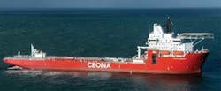
Recently, the two main cranes and vertical lay system (VLS) were fitted on Ceona's new deepwater field development vesselCeona Amazon at the Huisman yard in Schiedam, the Netherlands.
The 199.4-m (654-ft) long vessel, which will be the flagship of Ceona's growing fleet, is designed to perform in multiple pipelay and operational modes, including heavy lift and subsea construction. Its large storage areas allow it to carry 5,500 tons of flexible pipe or 8,500 tons of rigid pipe, with further storage space available on the 4,600-sq m (49,514-sq ft) main deck. This combination allows the vessel to carry sufficient quantities of rigid and flexible pipe, risers, umbilicals, or subsea structures (depending on requirements) to execute logistically complex projects in remote environments in a single trip, the company claims, minimizing the need for support cargo barges.
Lloydwerft constructed the hull at its shipyard in Bremerhaven, northern Germany. The hull is the third of a series of a proven drillship design – the others were commissioned by Noble Drilling. Ceona selected this concept because of its beneficial verified vessel response characteristics. The mid-ship moonpool is located close to the vessel's transverse axes, minimizing the impact of the vessel's motions on pipe stresses during installation. This should allow the vessel to remain in operation in relatively heavy seas and strong winds, Ceona claims. Additionally, the 8 x 13.5-m (26 x 44-ft) moonpool can accommodate the largest pipeline end termination structures.
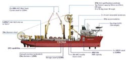
Huisman designed and builtCeona Amazon's 570-metric ton (628-ton) top tension VLS tower, an upgraded version of a tower used by Technip on the Deep Blue, and also the twin 400-metric ton (441-ton) active heave compensated cranes. These are capable of operating in tandem to lower large subsea structures, as well as handling long and complex subsea spools. In addition, the cranes can be used to support installations of mooring spreads for FPSOs, semisubmersible platforms, and TLPs.
Most of these features are derived from proven technologies, although the combination of the various components is unparalleled, Ceona claims. One new feature is the vessel's G-lay pipelay system (patent pending), which again combines tried-and-tested components and procedures. According to a presentation by the company's design engineering lead Jay Nguyen at the Deep Offshore Technology Conference in Aberdeen last year, the welding line is traditional S-lay. However, following welding the pipe is deflected around a stern wheel and installed through a conventional pipelay tower with two tensioners and 570-ton top tension in water depths of up to 3,000 m (10,000 ft).
To verify the functionality and capability of the proposed lay spread, the design team defined an "analysis roadmap" – an eight-point sequence of activities. The first was a beam element pull-through study to estimate the level of deck tension required as pipe is pulled through the system, and the maximum loads that will be applied on the stern wheel and tower wheel. This involved building a finite element (FE) model of the system, with the tower in the vertical position and the stern wheel shifted as far as possible to produce the largest free span. Analysis suggested sag and stress in the free span will reduce as deck tension increases, at the same time allowing the pipe to conform closer to the wheel profiles.
The company then developed a shell element FE model to assess pipe buckling potential followed by a parametric study to consider a range of uncoated, homogeneous pipes with varying outer diameters as they are pulled through the lay system. Shell elements were used to model each pipe type to allow observation of pipe ovalization as the pipe is pulled through the system. Results suggested buckling would not be an issue, with peak strain during pipelay occurring in the pipe's outermost fiber as it is pulled around the lay wheels, with a marginal ovalization of each pipe as it is bent around the tower wheel.
The next step was to establish whether a heavily insulated pipe could be bent around the aft wheel. The main concerns were quantifying the impact of bare field joints on the reeling process, and the effect of the geometric and material discontinuity on the ovality of the pipe close to these joints. The company analyzed a range of pipe diameters and wall thicknesses, including a syntactic polyurethane foam heavy insulation in thicknesses of 50, 75, and 100 mm. To optimize the model, the pipe string was revised to two coated pipe joints with the bare field joint centered, connected to beam elements modeling the remaining part of the pipe string. Then Ceona extended the complexity of the models beyond just shell elements for the study to quantify the impact of bare field joints. For this, they built the models using brick elements to obtain more accurate results during the pipe plastification stages of the process. Results suggested a heavy insulation coating will lead to increased ovalization of the pipe in the bare field joint region, compared with an uncoated pipe, underlining the importance of assessing property mismatches. Ceona has taken measures to mitigate localized ovality in a separate study.
Displaying 1/2 Page 1,2Next>
View Article as Single page
About the Author

Jeremy Beckman
Editor, Europe
Jeremy Beckman has been Editor Europe, Offshore since 1992. Prior to joining Offshore he was a freelance journalist for eight years, working for a variety of electronics, computing and scientific journals in the UK. He regularly writes news columns on trends and events both in the NW Europe offshore region and globally. He also writes features on developments and technology in exploration and production.