Real-time data images enhance rig safety, efficiency
Peter Torrione, PhD
Kenneth D. Morton, Jr., PhD
Mark W. Hibbard
CoVar Applied Technologies, Inc.
Modern drilling involves scores of people and multiple inter-connecting activities. Obtaining real-time information about ongoing operations is of paramount importance for safe and efficient drilling. As a result, modern rigs often have thousands of sensors actively measuring numerous parameters related to vessel operation, in addition to information about the downhole drilling environment.
Despite the multitude of sensors on today's rigs, a significant portion of rig activities and sensing problems remain difficult to measure with classical instrumentation, and person-in-the-loop sensing is often used in place of automated sensing.
By applying automated, computer-based video interpretation, it is possible to achieve continuous, robust, and accurate assessment of many different phenomena through pre-existing video data without requiring a person-in-the-loop. Automated interpretation of video data is known as "computer vision," and recent advances in computer vision technologies have led to significantly improved performance across a range of video-based sensing tasks. Computer vision can be used to improve safety, reduce costs, and improve efficiency.
Shale shaker analysis
Accurate, real-time information about the cuttings and mud on the shale shaker can be invaluable. For example, a distinct change in the shape and size of cuttings can indicate an unexpected change in the subsurface lithology. Similarly, accurate localization of the mud-front on the shale shaker can help ensure that the shale shakers are operating efficiently. However, the location and operational environment of shakers makes classical system instrumentation difficult and expensive. Computer vision provides a robust and inexpensive way to automatically and constantly track the shaker, mud flow, and cuttings state.
Particle analysis
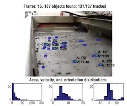
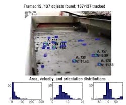
The image at lower left shows a frame of a shale shaker demonstration video enhanced with automated video processing to:
- Isolate individual particles on the shaker using object detection techniques
- Track the particles over time using a temporal-spatial-feature tracking algorithm
- Measure the particle sizes, shapes, and velocities using image morphology techniques. The resulting distributions of particle features (e.g., size, shape, velocity, eccentricities) form a statistical distribution (histograms below the image). These histograms can flag changes in these distributions, and bring that information immediately to the attention of the mud-logger or driller, significantly increasing drilling safety and efficiency, and helping provide better understanding of the lithology at the bottom of the well.
Mud front
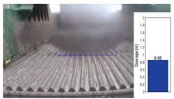
One of the largest day-rate expenses on a rig is the cost of drilling mud, and mud can be easily wasted if it is allowed to flow from the shale shakers overboard. Proper setting of the flow rate and choice of screen size is complicated, since the ideal parameters change with various mud and well parameters. Measuring the location of the fluid front would enable automated shaker monitoring, but developing classical fluid-front monitoring instrumentation has been problematic. Since the fluid front can be identified visually, computer vision techniques can automate this processing. The above image shows an example frame of a demonstration video showing how the fluid front can be automatically identified in a video of the shale shakers. A camera ordinarily measures object positions in units of pixels, which need to be converted to real-world units (e.g., inches) in order to be useful for automated control. This example video shows how it is possible to use knowledge of the camera parameters and location to infer real-world coordinates (the fluid front location) from the raw camera data.
Pipe handling
Some real-world tasks are so commonly performed by people that it can be difficult to envision how automated sensing could help save time or money. Pipe tallying, for example, is typically accomplished by a human, manually recording the number and length of joints added to the drillstring. Failure to tally pipe correctly can result in incorrectly calculated bottomhole location and poorly sequenced lithologies. Recent proof-of-concept studies have examined the ability of computer vision techniques to count sections of pipes as they enter and exit the camera field of view, as well as to measure the pipe diameter, lengths, and orientations with respect to the camera. The image below shows an example illustrating a tool for detecting, counting, and estimating the size and position of pipes on a drillstring as they are pulled out of the hole. Current results indicate reliable pipe-tallying capability and the potential for accurate pipe length and diameter estimates using a single camera oriented toward the drillstring.
Personnel identification
New generation rigs commonly include pipe-handling and mechanized rig-floor equipment. For the time being, person-machine-interactions are controlled solely by the equipment operator, and increasing rig autonomous action represents a major safety concern. A safe, automated rig can only be achieved by tracking the locations of all people on the rig floor at all times.
Many wearable technologies exist for determining personnel location (e.g., RFID), and on-board protocols are designed to make sure personnel are not in harm's way. However, both of these approaches require personnel to comply with protocols and voluntary usage of additional hardware, some of which may fail. Research in the application of personnel tracking and localization (personnel video monitoring, or PVM) in various real-world scenarios is ongoing. This work has resulted in a prototype real-time system capable of accurate personnel location identification in a wide array of environments, against complicated backgrounds.
The PVM system leverages multiple camera feeds to simultaneously find the people in each frame (camera field of view). Then, using knowledge about the camera positions and orientations, each person's location can be triangulated in rig coordinates, building a real-world spatial map of each person and his or her location. As people enter and exit the scene (work area), they appear as "dots" on a two-dimensional map of the rig floor; the information in that map can then be automatically leveraged to inhibit automated equipment actions when people are in harm's way.
The PVM system can operate on a computer rendering of a rig floor to show people moving about a realistic rig floor, with realistic camera placements. This technology can be used to illustrate how computer vision technologies can be used to not only detect people, but also to accurately estimate their location on the rig, thereby providing information to operators about safe and unsafe activities, as well as potentially inhibiting automated actions (e.g., the moving pipe-stand).
Less rigorous personnel detection approaches often fail under complicated lighting, background and partial occlusion situations, and effort is required to ensure that the system is robust to these scenarios. The technologies described here leverage state-of-the-art computer vision person detection algorithms, and are robust to varying lighting and complicated backgrounds. Furthermore, leveraging multiple cameras simultaneously allows PVM to track people even when they are occluded in several camera views.
Displaying 1/2 Page 1,2Next>
View Article as Single page


