Concrete FPS can succeed in ice-infested environments
Jan-Diederik Advocaat
Hilde Benedikte Østlund
Kvaerner
A concrete floating production and storage platform has the overall functionality needed for the challenging and harsh environment of the Arctic and subarctic. The CONDEEP design Concrete Deep Floater platform has an integrated buoy for quick disconnect and reconnect of risers and mooring systems. The Concrete Deep Floater is suited as a remote hub given its oil storage and topsides payload capacity. The design features include:
- Ice resistant concrete hull with acceptable hydrodynamic motions in severe weather
- Risers routed inside the hull, protected from ice exposure
- Mooring system with lines connected in the lower part of the structure with no ice exposure
- Quick disconnect for controlled disconnect within 12 hours and emergency/survival disconnect within three hours
- Reconnect through a combined riser and mooring buoy
- Large topsides capacity: 30,000-50,000 metric tons (33,069-55,116 tons)
- Oil storage capacity of 1.4 MMbbl
- Direct offloading system integrated in the topsides
- Substantially maintenance free concrete hull
- Possibility for local substructure construction
- Possibility for local topside integration with inshore completion.
The first stage of the CONDEEP concept development was presented in early 2014, and recent work has related to analyzing and verifying the platform motion behavior, as well as designing a combined disconnect/reconnect buoy. The result is a concept well suited for in the extreme weather conditions in areas such as the Barents Sea and the Flemish Cap.

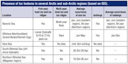
In Arctic and subarctic areas, ice action will always be a critical factor for any offshore structure. Ice conditions in different places may vary significantly. There are a number of ice features (level ice, ice ridges, land-fast ice, rubble fields, rafted ice, icebergs, and bergybits) that may interact with an offshore structure. In some areas, only first-year ice features are present. In others multi-year ice can be encountered and cause higher ice loads. Data concerning ice thickness, ice concentration, drift velocity, and physical and mechanical properties are required for ice load calculations. The final design of any offshore structure, whether fixed or floating, has to consider the actual ice conditions at the specific site.
The Arctic is a diverse region and the different areas require different design solutions. A simplified categorization system (divided into four category concepts) has been introduced for concept development in order to differentiate among the floater concepts suitable for the various environmental conditions.
Category 1 concepts.These concepts are suitable in areas with harsh weather but no ice exposure. A typical region where this is applicable is the Norwegian continental shelf where existing concrete floaters in operation are the Heidrun TLP and the Troll B semisubmersible.
Category 2 concepts. Floater concepts suitable in ice infested areas, provided that the normal ice load does not exceed the mooring system capacity, and is accounted for in the design as an accidental scenario only.
Developments falling under this category include the CONDEEP Deep Draft Floater, the concrete spar, and the circular concrete FPSO developed by Kvaerner for the Barents Sea. Common for these solutions is that the design accounts for quick disconnect of risers and mooring lines as an accidental condition. However, the design solution does not account for reconnect for continued operation after an accidental event. This philosophy permits a simple disconnect system. The concrete hull structures are robust and designed to operate without maintenance in ice infested waters with a large topsides payload capacity in order to enable operation as a hub in remote areas.
Category 3 concepts. This category is an extension of Category 2. The concepts are designed for a more controlled quick disconnect with the intention of later reconnecting the platform for continued production. These concepts will be suitable where having the ice loading exceeding the mooring system capacity is not only an accidental condition but included as an operation requirement. A disconnect operation will likely be costly and should as far as possible be avoided. Hence it may be recommended to combine these solutions with the possibility for ice management. Similar to the Category 2, the hull should be robust and designed to operate without maintenance in ice infested waters. Also, to reduce the probability of disconnection, the hull should be designed to withstand any ice impact with energy less than the mooring capacity.
Category 4 concepts. On-going development focuses on the areas where the ice loading exceeds the mooring capacity during a significant part of the platform's operational lifetime. Reducing the overall ice loads is the main focus of this development work, looking at the active and passive features of the hull geometry in combination with an active ice management operation.
Concept features
The main idea behind the CONDEEP floater design is to use the excellent features of the existing concrete floaters and concrete gravity based platforms located in harsh environments. Local content opportunities and project execution risks are factors driving a clean split between the topsides with large modules and a substructure that can be built in available graving dock facilities.
Continuous slip-forming is an efficient construction method. The water depths inshore and offshore affect the overall draft of the structure and are factored in when defining the construction methods.
The hull is designed using high-strength concrete and consists of a set of interconnected cylindrical cells capped with spherical domes. The geometry is suited to resist the large ice and wave loads, and external water pressure. Some cells are dedicated to oil storage while others are used for water ballast and buoyancy. The cylindrical cells are divided into compartments using concrete domes to ensure that damaged stability criteria are met. The hull accommodates a large, protected oil storage system of 1.4 MMbbl. An internal protected riser system will be both robust and cost-effective with the option for steel riser systems down to the wellhead. With the oil storage located 77 m (253 ft) below sea level, it is well protected from conflict with surface vessels. The outer diameter of the structure with the cellular layout at the top provides for an efficient topsides design and cost efficient topsides mating operation. No additional topsides steel weight is required for the deck-mating load case.
Topsides weight is critical for floaters, and the robustness to accommodate increased topsides weight is important. The presented floater concept is designed for a topsides weight ranging from 30,000 to 50,000 metric tons. This, combined with a bilge keel arrangement and the selection of stability characteristics, will control the motions from waves and wind loading. The floating draft is kept constant during operation by load compensation tanks. The freeboard to underside of deck can be adjusted to the specific field requirements to reduce challenges with ice spray and green sea on deck.
Hydrodynamic motions
The CONDEEP Floater has good characteristics for heave and pitch motions while operating.
Model tests confirm the analysis and serve as the basis for site specific motion analysis and hull configuration optimization. This includes non-linear behavior in extreme wave conditions. Model test waves were based on typical Barents Sea conditions.
The model test confirmed the excellent motion characteristics in the operating conditions. For the 100-year condition the maximum estimated pitch is in the order of 7°. For the 10,000 year return period the maximum estimated pitch was found to be about 11° (Barents Sea conditions).
The heave motion is in general favorable for concrete hull concepts. For the concept, the 100-year return period heave is 4 m (13 ft).
The topsides is designed with a long and narrow rectangular deck frame of 68 m x 50 m (223 ft x 164 ft). The layout provides maximum distance from riser area to the living quarters for safety. Riser routing is from the main manifold down into the center shaft. The internal routing protects the risers from external impacts such as ice and vessel collision.
Riser disconnection will be performed at the topsides as the risers are dropped down for hang-off on the buoy through steel conductors. Reconnection will be through the same conductors, using pick-up wires from the buoy.
For deeper water, a favorable solution could be a rigid steel riser tower combined with flexible risers. The choice of flexible versus steel catenary risers or a riser tower depends on the actual field.
The CONDEEP Floater is designed with a wet oil storage system in the lower part of the hull, using the lower outer cells for storage. The storage volume can be increased by adjusting the geometry of the cells.
Crude oil is stored on a cushion of displacement water. The design has an internal under pressure in the storage cells achieved by connecting the displacement water side of the storage to a control level tank. The control tank has a free water level 25 m (82 ft) below sea level so the under pressure achieved in the storage tank assures no oil spill to sea in the unlikely event of tank leakage. The sea water side of the storage system replaces oil to and from the storage to keep the storage cells at a constant under pressure relative to the surrounding sea. Displaced water during oil production is pumped up to the topsides for control and optional treatment, or reinjection into the reservoir.
Mooring capabilities
Quick disconnection of the platform is required in certain regions and is one of the main features of this design, and incorporates a safe reconnection option. Feasibility design has been performed for a mooring system and riser buoy located in the center of the lower part of the hull, with all risers and mooring lines connected to the buoy. The design calls for 16 chain/polyester tautleg mooring lines connected to the submerged buoy and 21 flexible riser connections. The total number of lines depends on the environmental conditions at the field, accounting for the 100-year intact condition, the 100-year condition with one-line failure, and the 10-year condition with two-line failure. Suction anchors are assumed for the sea bed interface.
The main phases for the platform installation include:
- Initial installation of the buoy involves towing it to the field with parts of all mooring lines pre-rigged. One by one, the mooring lines would be installed. At completion the buoy will be left at installation draft of -127 m (-417 ft)
- The floater with topsides installed is positioned at safe draft of -117 m (384 ft) to give a 10 m (33 ft) clearance between the buoy and platform
- A combined deballasting and anchor/wire would pull and guide the buoy into position
- At completion, the combined buoy and platform would be deballasted to operating draft of -112 m (- 367 ft); this will give the final tensioning of the mooring system
- Riser pull-in would be done one-by-one from the topsides through the buoy and the pre-installed casing in the center shaft of the platform. Ballast levels in the buoy will be adjusted as required using ROV-assisted deballasting to give the specified vertical load into the platform.
For quick release, the risers would be disconnected at topside level and dropped through the conductors to the top of the buoy. The weight of the risers are be balanced by the buoy buoyancy system.
Typically, the buoy would have a ballast system with closed and open compartments that can be operated by an ROV to ensure the appropriate vertical load is transferred to the platform.
Main phases for the platform disconnection and reconnection are disconnect and drop risers from the topsides and down onto the buoy, disengage the buoy by ballast/air release and by disconnecting the locking bolts, buoy will rest at a safe draft below iceberg keel and reconnect as per the initial installation.
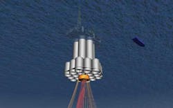
Buoy lay-out
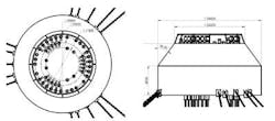
The cone shaped buoy is designed to take all the required risers and mooring line loads. During release the buoy will be lowered as one complete unit with risers and mooring lines connected. During reconnection the buoy must be deballasted prior to being pulled upwards and guided into position where it is then locked, similar to initial installation. Access to the water filled void above the buoy would be by ROV through the tricells. The center shaft will be dry from the top to the lower dome. Typical buoy dimensions could have an overall diameter of 34 m (112 ft) and a total height of 15-20 m (49-66 ft).
The towing spread will position the floater typically within ± 10°. The guiding system will be designed to take this offset. Guide and locking bolt arrangement will hold the buoy into its final position. Vertical loads and torsion forces will typically be transferred through the load bearing ring at top of the buoy. During the release operation, the buoy will be deballasted and lowered to safe distance allowing for proper under keel clearance for any iceberg.
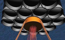
The top of the buoy is designed to allow for all 21 flexible risers to be lowered to rest on top of the buoy. Overall lay-out is designed for working space between risers.
Disconnection schedule
Having all mooring lines and risers connected to one submerged buoy allows for an effective disconnect and reconnect operation. With riser hang-off at topsides elevation during normal operation, a safe and quick procedure can be developed for the release. When the buoy is released, it will go to a predefined draft using the buoy ballast system. The floater will be free from the mooring and riser system for tow.
In disconnected mode, the buoy is positioned in floating equilibrium at a predefined draft to give sufficient under keel clearance from any approaching icebergs or other threats.
During reconnection, the process would be reversed. The possibility of ballasting and deballasting the platform allows for posttensioning and adjustment of the mooring lines as required.
The time required to disconnect the riser and mooring buoy from the floating platform has been assessed for two cases:
- An extreme disconnection where the risers, flowlines, and subsea wells are prepared for quick restart to production mode
- A survival disconnection whereby the platform is disconnected as quickly as possible during an emergency situation and the impacts of a potential future reconnect is not considered.
Typical disconnection schedule for a controlled disconnect scenario, prepared for quick restart:
- Preparations: 3-9 hours, plus mobilization time for towing vessels
- Disconnect operation: 1-2 hours
- Total time until start platform tow to safe haven: 4-11 hours
Controlled disconnect preparation activities include:
- Mobilization of vessels and required manning
- Demobilization of platform manning
- Preparations for process plant shut down
- Production stop, subsea wells; close subsea SSIVs (subsea isolation valves)
- Prepare risers and production lines (depressurize and fill with inert gas as applicable, close riser EVs)
- Disconnect and drop risers from topsides down onto buoy
- Connect towing vessels to floater
- Releasing buoy from platform by ballasting/air release
- Disconnect locking bolts
- Drop buoy to safe draft (below iceberg keel)
- Tow platform to safe haven.
The minimum preparation time for emergency/survival disconnect is estimated to about three hours and includes production stop at subsea wells, closing of the riser SSIVs, depressurizing the risers/closing the EVs at platform topside, shut down the processing plant, prepare the buoy for disconnect and connection of the towing vessels.
The time required to reconnect risers and production restart has not been assessed at this stage, as this will be closely related to the specific field and platform operating philosophy and design.
Acknowledgment
Based on a paper presented at the Deep Offshore Technology International Conference & Exhibition held in Aberdeen, Scotland, Oct. 14-16, 2014.