P.2 ~ New infield pipeline liner offers effective rehab option
View Article as Single page
IFL offers a fast, economical option to new-lay pipeline replacement. It can be used to rehabilitate an existing subsea pipeline where:
• It is desirable to extend the service life of the pipeline beyond the period of operation on the original design
• Unforeseen operational parameters, such as CO2 or SRB corrosion, have caused the pipeline to reach the end of its useful life ahead of schedule. The pipeline may or may not have at that point already been shut-down and abandoned for safety and/or environmental reasons
• Routine inspection of the pipeline has shown greater than anticipated corrosion. Unless corrosion is arrested, the pipeline will fail at a predictable point in the future earlier than the design life
• In instances where pipelines have been decommissioned or abandoned due to integrity related issues.
Overall, pipeline liner lengths depend on the pipeline diameter, configuration, and number of short radius bends. However, trials indicate that the rehabilitation of a typical 6- or 8-in. diameter hydrocarbon flowlines could be feasible over distances of up to 10 km (6.2 mi).
Replacing a pipeline and abandoning/removing the old one usually represents a major engineering, procurement and installation campaign, and an equally major capital expense.
The insertion of an IFL liner into a defective pipeline is a process of lesser magnitude in terms of planning, implementation, and expense. In terms of project turn-around, IFL might be able to achieve in weeks what may otherwise take years with conventional pipelay replacement, especially if the necessary pipelay barges for conventional laybarge are not available in the region.
IFL installation procedure
A thorough inspection of the existing subsea pipeline prior to the detailed planning of any IFL liner rehabilitation project is mandatory, as is the collation of all data relative to the prevailing operating parameters and conditions. Inspections can be by intelligent pigs or other external remote inspection tools such as the MTM Aqua.
This data is used to assess the general condition and remaining wall thickness of the pipeline, and to verify the IFL liner size requirements in the event that an enhanced tight-fit, high-pressure liner is required.
Prior to offshore deployment of the marine spread, the host pipeline must be decommissioned, cleaned, and gauged ready for the liner insertion.
The IFL liner material, although manufactured in a circular profile, can be temporarily flattened for transportation, and reeled onto a transportation drums sized to fit a conventional shipping containers. Each drum can be loaded with up to 5 km (3 mi) of IFL liner, depending on the liner diameter. These drums are then shipped to an onshore location within the destination country, usually a marine supply base, where they are further processed into a folded liner format prior to being sent offshore for installation.
The IFL liner installation is fast, reaching speeds of approximately 10 m/min (32.8 ft/min), inserting a typical 2-km (1.2-mi) liner in no more than 3.5 hrs.
The IFL liner drum is, wherever practical, positioned on the offshore platform structure, or when necessary, on the deck of a work boat so the liner can be unspooled.
A feeder cable is fired through the pipeline during the final cleaning and gauging procedure, and this is used to pull back an installation winch cable through liner for connection to a towing head, which is located on the leading end of the liner.
During the engineering phase of a rehabilitation project, the specific winching loads necessary for the liner insertion are analyzed using the proprietary predictive IFL software. The winch packs used for the actual installation process are equipped with load cells and over-ride devices so in the event of greater than predicted load during the winching, the operator is alerted. In such a case, the devices can automatically cut out at a given load if the engineered safety factor relative to the liner yield strength is approached. In reality, for most liner insertion situations in the 0.5- to 5-km (0.3 to 3.1 mi) range, the insertion forces are no more than one-tenth of the liner tensile yield strength.
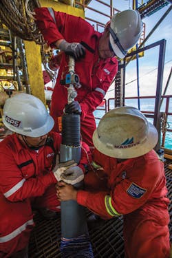
Prior to the liner installation, the IFL end termination coupling devices are installed at the riser flange locations. Once the IFL liner is drawn through the entire pipeline length, it is re-rounded by filling with either air or water. The liner, manufactured to the same diameter as the host pipeline bore, then expands to form an intimate fit with the inner wall of the host pipe.
With the liner fully re-rounded against the wall of the host pipeline, the last task is to install the end termination inserts. These ensure reliable compression seals and restraint at the liner ends. The re-lined pipeline can then be hydrotested conventionally and all topsides pipe work can be reconnected. After that, the pipeline is ready for re-commissioning and for its new, extended life of operation.
The future
The IFL development project has delivered to Petronas a viable alternative way to replace deteriorated offshore pipelines.
Following the successful conclusion of the IFL development, APS has installed several infield liners for the Petronas subsea pipeline network in Malaysia, whereby re-commissioning of previously shut-down pipelines was enabled in summer 2013.
Petronas favors the option of pipeline rehabilitation over that of new-lay pipeline replacement, and in so doing, will drastically reduce its offshore opex. •
The author
Robert Walters is the IFL Global Project Director and Chairman of APS.

