Careful planning precedes successful platform installation at Ekofisk
Stig Minsaas
RC Consultants
Stuart Paterson
Saipem Ltd.
Vikrant Joshi
Gaurang Haldipur
ConocoPhillips
The Ekofisk field, operated by ConocoPhillips Norway, is located in the southern part of the Norwegian North Sea. The field has been in operation for more than 40 years. The Ekofisk complex comprises nine platforms and bridge connections. The newest platforms are the wellhead platform 2/4Z and the field center and accommodation platform 2/4L, which were installed in 2013.
Since the development started early in the 1970s, the complex has been a field center and hub for the production from the Ekofisk field itself, and from the other fields in the Greater Ekofisk area. In addition, production from other fields in the area is transported via the Ekofisk complex to the receiving terminals in Emden, Germany, (gas) and Teesside, UK (oil).
Upon hook-up and commissioning in 1Q 2014, the 2/4L accommodation platform will be the new field center, replacing all functions presently located at the aging 2/4H and 2/4Q platforms. The platform has a total accommodation capacity of 552 single occupancy cabins, and will be the world's largest offshore living quarters platform and serve as a safe haven for the Ekofisk complex. It will also provide office space, storage areas, workshops, an emergency center, fire water supply, and telecommunications controls for the Ekofisk complex.
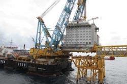
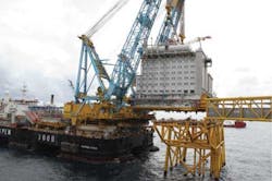
The 2/4L topside facilities were engineered and constructed under an EPC contract awarded to SMOE Pte. Ltd. The transportation and installation execution scope was awarded to Saipem UK Ltd. in 2010. The topsides were successfully installed on top of the jacket in August 2013. The jacket and the bridge structures connecting 2/4L to the Ekofisk complex were installed in 2012.
The topsides weighed more than 11,200 metric tons during offshore installation, representing one of the heaviest offshore lifts using dynamic positioning (DP) by theSaipem 7000 installation vessel. Due to high lift weight, tight clearances, and environmental conditions, an extensive engineering and planning effort was carried out to ensure a safe and successful offshore installation campaign. This included:
Setting up installation constraints/limits
Installation limitations in both lift weight and dimensions were established for the installation of the 2/4L topside. These limitations were based on the lifting capabilities of theSaipem 7000 (S7000) by way of both capacities of the cranes, their geometry, and resulting clearances to the topsides module at all stages throughout the lifting operation.
An initial installation study checked the lift configuration and clearances during preparation and lift-off from the transport vessel and at hover over the jacket prior to set-down. From this study, exclusion zones were developed. No structure, equipment, fixture, or fitting was allowed to extend into this area during the offshore lifting operation. These exclusion zones were modeled into the designer's PDMS model of the topside, and the designers of all disciplines were made aware that no items were to encroach beyond this boundary. This ensured that no damage or hindrance was experienced during the installation.
The exclusion zones were based on nominal clearances of 5.0 m (16 ft) to theS7000 at lift-off and during setting of the topsides. Two conditions were considered. For the case just before lift-off from the transport vessel, clearances were critical to the hull structure of the S7000 up to the upper deck, corresponding to topsides levels 0 to 3. For the hover over the jacket, a minimum clearance of 1.5 m (4.9 ft) under the topside stabbing cones was assumed, with the S7000 at operation draught of 27.5 m (90.2 ft) and using sea level at LAT. In this condition, clearances to the crane boom were critical.
An additional case considered was to cover clearance for the tail swing of theS7000 cranes with the transport vessel and topside moored across the S7000 bow. For this case an allowance for 2° of transport vessel roll and a further minimum 3 m (10 ft) clearance was considered.
Topside lift rigging design factors
Due to the weight of the deck, it was agreed with the marine warranty surveyor (MWS) that reduced lifting factors would be used for the rigging calculations to improve the capacity ofS7000 for the lift. The rigging was constructed from high strength steel wire, reducing the weight of the rigging and increasing the allowable weight of the topside.
At a minimum lift radius of 50 m (164 ft), each crane had a static hook capacity of 6,000 metric tons in tied back mode. East/west center of gravity (COG) zone/envelope of 1.75 m (5.74 ft) offset from the center of lift points. The topside was designed with four lift trunnions; each hook of the crane connected to two lift points. Rigging used for the lift was newly purchased.
Tilt was controlled by the relative levels of theS7000 crane hooks. Grommet lengths were selected to suit the most likely COG. Grommet lengths were selected on the basis of minimum allowable angle of 70°.
The following lift design factors were applied within the rigging design:
- Weighing inaccuracy: 1.015
- COG envelope inaccuracy: 1.01
- Transverse tilt: 1.01
- Yaw factor: 1.05
- Dynamic amplification factor: 1.10.
The chosen lift rigging was:
- Doubled grommet 287 mm diameter, 133.09 m long, 39.8 metric ton weight and CGBL (calculated grommet braking load) of 7,344 metric tons (2 each)
- Doubled grommet 287 mm diameter, 130.74 m long, 39.1 metric ton weight and CGBL of 7,344 metric tons (2 each).
The weighing inaccuracy factor was reduced further to 1.01, with agreement from both Saipem and the MWS, upon receipt of the weighed weight report from SMOE, to gain extra capacity to allow the lift to be performed without the need for additional weight shedding apart from the helideck. As a condition of this reduction, a strict policing program was implemented at the fabrication yard prior to sail-away.
S7000 DP capability analysis
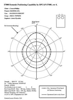
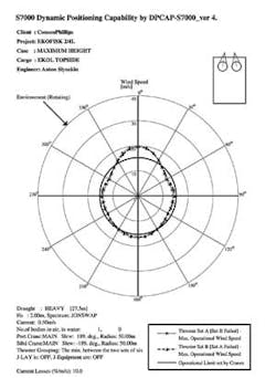
The DP capability analysis is a tool used to derive wind speed limits for the installation. The windage area of each module goes into Saipem's in-house program, and given other fixed environmental criteria, a study defines a limiting wind speed. The limiting wind speeds were based on the following assumptions:
- Topside lifted on the main hooks of both cranes at the point of highest lift
- Fixed current velocity of 0.5 m/s uniform with depth
- Intact case and worst case failures
- Significant wave height of 2.0 m (JONSWAP wave spectrum formula)
- Wind, wave, and current co-directional
- Ballast to heavy lift draught
- Both port and starboard cranes with lift radius of 50 m, slew angle of 188.56°
- IMCA specifications for DP capability plots
- Horizontal forces and yaw moments due to wind on the lifted item calculated from the projected area and center of pressure
- Wind load calculations on the topside considers shape coefficient of 1.0 and simple cuboid shape
- Sensitivity analysis was carried out for
- a. Crane radius change of +/- 6 m horizontally and +/- 3 m vertically
- b. COG of +/- 6 m radially and +/-3 m vertically
- c. Equivalent crane boom radius and slew angles considered.
The intact results showed that the DP system provided sufficient capacity to withstand wind speeds much more than the limit for the crane operations (30 knots).
For the worst failure case at approximate headings of 60° and 300° (with respect to the bow ofS7000), the maximum allowable wind drops to below the crane operability limits. This was considered acceptable due to the small probability that this wind speed would be exceeded during the proposed installation months.
The study also showed that the limiting wind speed does not vary significantly with the change in crane radii and COG movement. This analysis ensured that the operations were safe with regards to station-keeping capabilities of the vessel.
Topside dynamic lift analysis
The dynamic lift analysis of the 2/4L topside covers the range from pre-rigging to the pre-set-down hovering ( i.e. bottom of the topside stabbing guides 1.5 m above the jacket legs) conditions. The analysis in time domain was performed using LIFSIM software (developed by MARIN). The hydrodynamic properties for theS7000 were supplied by MARIN, while those for the transportation vessel Osprey were derived using software MOSES. FORSIM software was used to generate wave loading time history.
The analysis was carried out with the following assumptions:
- 1. Sea states with irregular waves of 0.5 to 2.0 m significant height and 4 to 8 second wave peak period (5.7 to 11.3 m wave zero crossing period). Regular waves of height 0.25 to 1.0 m and period of 8 to 12 seconds were also considered to represent swell seas.
- 2.S7000 at lift-off draft
- 3. The inherent structural damping properties of the rigging
- 4. Lifting grommet lengths selected such that the topside would remain nominally level once lifted
- 5. Neither wind nor current considered in the simulation because its dynamic effects are negligible and the steady force they produce would be counteracted by the DP system
- 6. The lift was divided into pre-lift, pre-tensioning, and lift-off stages, during which the Osprey was moored toS7000.
In pre-lift, hooks are lowered to pick-up slings. The relative motion between the crane hook and the point on the laydown platform should be no more than +/- 1.5 m horizontally and +/- 0.75 m vertically.
In pre-tensioning, the topside load is transferred by a combination of ballastingS7000 and picking up crane blocks. Limiting criteria for this stage included:
- No separation more than 100 mm between the topside and its supports
- Maximum dynamic load on grillage of 6,500 metric tons (row B & G)
- S7000 roll and pitch less than 1°
- Boom tip heave motion less than +/-1 m
- No slack slings.
In the lift-off stage, the dynamic hook and sling load were not to exceed maximum allowable dynamic loads and no slings to go slack. In case of re-impact between the topside and transport vessel supports, vertical load limit of 6,500 metric tons to the supports would apply.
During post-lift, the topside would be hanging from the crane hooks and ready for the final position on the jacket. Dynamic interface betweenS7000 and topside was a prime concern in this stage. Further, in this stage, there was to be no vertical distance less than 1.0 m between the topside and the HTV Osprey and no horizontal distance less than 5.0 m between the side of topside and the bow of S7000. While the topside is hovering above the jacket legs, there would be no horizontal distance less than 3.0 m between the side of topside and the bow of S7000, and the horizontal radial distance between the stabbing guides of the jacket and topside could not be greater than 0.62 m for at least 90% of the time (30 minutes).
7.S7000 pitch/roll motion should not exceed +/- 1° and the boom tip heave motion should be less than +/- 1 m.
The following conclusions were derived from the dynamic analysis:
- 1. Most favorable heading for the lift was beam (port/ starboard) seas toS7000 and most unfavorable was longitudinal seas (head/ aft) to S7000. Most favorable wave heading can be chosen for S7000 with DP mode.
- 2. 75% pre-tension was optimal. At this stage, operability was governed by premature lift off and exceeding rigging utilization.
- 3. Parallel separation between topside and HTV was achieved with the final sling lengths adjusted for the expected offset of COG from the lift points and the pre-ballasting of the HTV for any expected residual tilt for topside during lift-off.
- 4. The pre-hook up stage was generally most challenging, followed by lift-off. There was good operability for both stages in the most favorable headings.
- 5. The vertical/ horizontal gap between the hook and the point beneath on the laydown platform were the overall governing criteria. The rigging utilization is also critical to lesser extent especially in higher sea states.
- 6. Based on topside stabbing on the jacket analysis, it was concluded that the topside could be safely installed on the jacket. Longitudinal (head/aft) and beam toS7000 were the most favorable heading and quartering to S7000 was the worst heading.
- 7. The main limiting criteria were the horizontal movement of the primary stabbing guides above the jacket legs.
- 8. The reduction in operability was only in highest periods due to the increasedS7000 pitch motion.
Weight and geometry limitations were determined based on the lifting capabilities of theS7000 cranes. These limits were used to determine the maximum allowable lift weight for different COG ranges and battery limits for dimensions. The limiting parameters were communicated to all involved parties who needed to strictly control these limits. Controls in place during the project management included an accurate and detailed weight and COG monitoring database based on the PDMS model issued monthly to all parties.
The topside was weighed two times and the weighing results reconciled against the weight control database. The weighing results were in agreement with the weight and COG from the predictions established based on the weight control report. Contingency plans were established for weight shedding by removal of items, if required, following the final weighing and COG location calculations prior to sail away. It became evident that the helideck needed to be installed as a separate lift. The helideck was modified to be transported in situ, removed from the topside and back-loaded onto theS7000 deck upon arrival in Norway, and installed after the topside lift.
Conclusion
With execution of the engineering, planning, and project management as described, the offshore lifting operations were safely executed as planned without incident.
A final interesting aspect of the offshore installation was the long transit made byS7000 once the 2/4L topside had been lifted from the HTV. To better control mooring operations, it was agreed that the HTV would use a bow anchor. Since the Ekofisk field is covered with seismic cables, the permitted anchorage was approximately two nautical miles from the installation location. This resulted in a transit with the topsides on the hooks lasting over two hours.
Acknowledgment
The authors acknowledge permission to publish this article from ConocoPhillips Skandinavia AS and co-venturers, including Total E&P Norge AS, Eni Norge AS, Statoil Petroleum AS, and Petoro AS.