Industry collaboration works to advance subsea processing technology
Roy Long
US Department of Energy
Improving safety, reliability, and performance in deepwater development are the principle goals of the US Department of Energy Office of Fossil Energy's (DOE) implementation of the Energy Policy Act of 2005. The program, created by an act of Congress and administered by the Research Partnership to Secure Energy for America (RPSEA) under the direction of DOE's National Energy Technology Laboratory (NETL), funds research, with additional funding and research by industry and academic partners, in technologies key to ensuring a secure energy supply for the United States.
Research in subsea production and processing has been an important component of the program. Within the deepwater program, a series of projects undertaken jointly by RPSEA and GE have worked to develop subsea processing technology to lessen the need for deepwater surface production facilities and extended tiebacks.
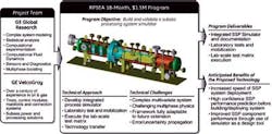
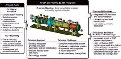
The program began with development of a process simulation tool designed to model subsea processing systems (SPS) for oil and gas. The intent was to provide an industry standard to evaluate SPSs performance, and to help bridge technology readiness level (TRL) gaps between operation engineers and facility suppliers. The program deliverables included simulation architecture, a functional simulator, procedures and documentation, experimental validation, and experimental facility availability.
The program's key objectives included:
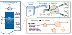
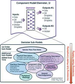
Objective 1. Develop a library of robust analytical unit models, with standardized interfaces, for compact separation devices operating in a subsea multi-phase flow environment. Standardized unit models allow the buildup of complex systems.
Objective 2. Develop a robust process simulator combining the analytical unit models from Objective 1 to provide for the following major features:
- Prediction of both steady-state and transient performance
- Expandability at the component level to accept more accurate analytical component descriptions as they become available from ongoing research and experience
- User configurability
- Interface with existing upstream industry-standard production simulators.
Objective 3. Develop a lab-scale test facility and testing protocols for the validation of both the analytical models and the simulator performance. This objective has importance for both developing unit models and validating the resulting system models, as well as the processes and methods used therein. This objective was accomplished through the creation and use of a test loop facility. The chosen test case is a horizontal three-phase (saltwater/oil/gas) gravity separator.
Objective 4. Develop a methodology and associated procedures for using the simulator to determine the operational envelope for various process designs. This was achieved through the development of a statistical methodology and toolkit in MATLAB, the technical computing language and interactive environment for algorithm development and data analysis.
Objective 5. Using the lab-scale test facility and protocol, simulator performance was validated by executing a test plan for evaluation over a wide range of conditions:
- Operating envelopes
- Transient stability
- Process control logic.
Using the simulator to model various components of SPSs resulted in several research and development projects, among them the design of subsea electrical provision and distribution systems to power subsea processing components.
AC and DC alternatives
Subsea electrification is seen as a key enabler and an integral part of the processing and control for deepwater oil and gas production. Subsea processing systems such as pumping, compression, and separation require the deployment of equipment that may include variable frequency drives (VFDs), electric motors, switchgears, and uninterruptible power supplies (UPSs) in close proximity to the loads on the seabed, connected via dry and wet mate connectors. Their control requires electric actuators and valves for "All-Electric" trees and highly reliable power supplies for communication and control at long step-out distances. For such applications, bulk electrical power needs to be effectively delivered from onshore or offshore platforms where power is generated, to electric loads on the seabed.
The main drivers for the power delivery system are very high reliability and maintainability. In addition, it is desirable that the system be efficient, low cost, and of high power density. Electric power can be transmitted and distributed over long distances either by alternating current (AC) or direct current (DC).
Conventional HVAC system
The high-voltage AC (HVAC) power transmission and distribution (T&D) system is a mature and proven technology for land-based applications and relatively short offshore tiebacks. The system is configured differently when single load or multiple loads need to be supplied.
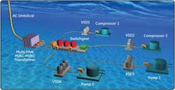
Single load application. There are currently two AC power transmission options to supply power to a single subsea load. For these two AC power transmission options, multiple topside VFDs and a power umbilical with multiple three-phase submarine power cables are required to supply more than one subsea load. Another potential problem is the power transmission with variable frequency, which can increase the risk of electrical resonance and is very challenging to control.
In the first option, a medium-voltage topside VFD is used to generate a variable frequency voltage, which is directly connected to a subsea motor through a submarine power cable. This option has been used in several applications such as in the BP King subsea pump project. The VFD generates medium voltage (e.g., 9 kV) and supplies all power required in the system, including the reactive power required by the submarine cable. The transmission distance is up to 27 km for a subsea pump of 1 MW at 6.6 kV. The VFD rating can be significantly high for longer distance; therefore this option is limited to power ratings up to 3 MW and distances up to approximately 40 km. In the second option, a medium-voltage (e.g., 6.6 kV) variable frequency voltage is generated by the VFD and boosted by a step-up topside transformer for transmission (e.g., 12 to 42 kV depending on the tieback distance) via a submarine cable. On the receiving end of the cable, a subsea transformer is used to step down the voltage to supply a subsea motor (e.g., 6.6 kV). This system configuration has already been successfully applied to several field developments, such as the Lufeng field in Hong Kong and Tordis Field in the North Sea. However, it is limited to shorter distances (i.e., tens of km depending on starting torque requirement).
Multiple load applications. When multiple independent loads need to be supplied at a relatively long step out distance, the cost of power umbilical becomes a limiting factor if topside VFDs are used. One technical option to deliver power to subsea loads was pursued for the Ormen Lange field development, where the tieback distance is about 125 km and power requirement for the subsea loads is approximately 60 MW.
However, due to cable capacitance, in addition to the active power required by the loads, a large amount of reactive power needs to be supplied, leading to large and expensive cables with high current rating and losses. This also leads to more expensive umbilicals with higher costs of installation and retrieval. This issue is especially severe for longer step out distances. For example, to supply approximately 60 MW of active power loads on the seabed with 125 km step out, it is necessary to provide 70 MVAr reactive power and 2 MW power loss under no load conditions, and 50 MVAr reactive power and 4 MW power loss under full load conditions. The transmission distance of the conventional HVAC technology is, therefore, limited to about 90 miles for a given cable, with inductive compensation. The transmission distance of the AC solution can be extended by reducing the AC frequency.
DC alternative
A better way to overcome cable capacitance and reactive power issues for long distance power T&D is to use direct current (DC) instead of AC. HVDC is an established technology for onshore applications. The present voltage-source converter based HVDC technology (HVDC PLUS, HVDC Light), achieves high DC voltages by connecting a large number (e.g., up to 300 per converter) of specially designed and packaged power semiconductor switches or large number power modules in series. However, the acceptance of HVDC systems with respect to efficiency, reliability, and controllability will strongly depend on the availability of HVDC circuit breakers (CBs), making them one of the key enabling technologies. The difficulties in utilizing HVDC CBs can be attributed to the demanding requirements on the CBs in DC systems, which are quite different due to the absence of natural current zero crossings. The breakers have to fulfill the basic requirements of creating a current zero crossing to interrupt the current and dissipate the energy stored in the system inductance. Therefore, the converter substations are bulky with limited flexibility; they are also complex to transport, marinize, install and retrieve, reducing the system flexibility for future field expansion. Even if these modern HVDC systems are marinized, assuming scenarios where loads are to be located 10 km from each other, they will require a subsea transformer which will supply subsea switchgear and a set of 10 km three-phase subsea cables to connect to each subsea VFD with an input transformer. All these components will, therefore, increase the system complexity, number of subsea components, and distribution losses.
An example of modern HVDC application is the Troll A offshore platform. It has a tieback distance of about 70 km and a water depth of about 300 m. The receiving end inverter station is a voltage source converter based HVDC with a rating of about 88 MW. The receiving end inverter is not subsea; it is installed on the platform. However, for longer tiebacks and deeper waters where a platform cannot be built, the HVDC converter station, as used in Troll A, becomes challenging to transport, install and retrieve on the seafloor due to its physical dimensions and weight. Moreover, any failure on the receiving end unit will have an impact on the overall field production. The Troll converter station caters to a single load (HV motor) and is not directly scalable for connection to multiple loads; hence it has reduced flexibility for future field expansion.
MSDC architectures
In order to overcome the issues related to conventional AC and present DC transmission systems for long-distance subsea tiebacks, a set of modular stacked DC (MSDC) architectures was explored. In contrast to conventional HVDC, the MSDC technology achieves the required DC transmission voltage by stacking a number of power converter building blocks in series, both on the sending end and at the receiving end of a DC bipolar cable. From the sending end, the system is controlled to behave as a current source system. In terms of protecting the system, this creates a substantial advantage compared to the HVDC system which is controlled to behave as a voltage source. The protection is not realized by breaking the current operation; instead the faulty module is bypassed which makes the protection much smaller and easier to accomplish. On the other end, each subsea module acts as receiving end power converter and integrated VFD system. Since each building block is similar to a conventional drive, the subsea VFDs are smaller and easier to transport, marinize, and retrieve.
Moreover, the modularity of the MSDC architecture renders the system fault-tolerant and capable of operating in a degraded mode. The architecture is also highly reconfigurable as the field matures and the loads evolve over time.
Compared to AC technology, it is apparent that the number of subsea components is vastly reduced (no distribution transformer, and no switchgear), potentially reducing the cost and improving system reliability and availability.
