Liner drilling enables operators to reach new depths
Maurilio Solano
Baker Hughes
Deepwater drilling into complex reservoirs located miles below the seafloor presents common challenges to drilling contractors. Drilling through weak or lost circulation zones may prevent the liner from reaching total depth, leading to increased well construction costs and limiting the production potential of the well. These challenges may be so insurmountable by conventional drilling processes that the operator is forced to P&A the well.
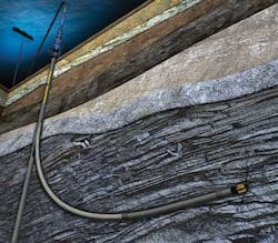
The process of liner or casing drilling, in which the well's liner or casing string is used as part of the drillstring, can be a cost-effective solution that addresses many of these challenges. Liner/casing drilling is an integrated services solution that can shorten drilling time and costs, reduce non-productive time (NPT), lower the risk of drilling through trouble zones, and help ensure that the liner reaches total depth.
In standard drilling practices, an unstable formation may collapse before or after the bottomhole assembly is pulled out of hole, which may cause drillstring sticking and loss of hole gage. Drilling with liner mitigates the risks associated with unstable formations, keeps the hole protected, and allows the liner to reach its desired position. By imparting stability to the wellbore, liner drilling means that longer hole sections are possible.
Liner drilling also minimizes the risk of lost circulation if the mud weight exceeds the fracture gradient of the formation, which can cause drill pipe to get stuck, resulting in fishing jobs, side tracks, or P&A operations. Because the liner is permanently installed during drilling, lost circulation and formation damage are minimized, costs are reduced, and production rates can be higher at the outset.
Conventionally drilling through trouble zones can be challenging. The upfront analysis, pre-planning, and understanding of the reservoir are critical to success, and required to understand the geology and structure of the reservoir. Regardless of which liner drilling architecture is deployed, each system component must handle the torque and loads created during drilling operations, including rotation, reciprocation, and vibration.
At the same time, the liner drilling system must work seamlessly as part of the overall well construction. For example, the system must be compatible with the mud system to ensure the wellbore is efficiently cleaned during drilling without significant loss of mud into the formation. This is achieved through comprehensive project management and collaborative planning with both the operator and other service providers on the job.
A custom-built solution
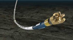
All liner drilling assemblies have in common some type of non-retrievable casing drill shoe mounted on the end of the casing or liner. The shoe comprises polycrystalline diamond compact (PDC) cutting structures and drillable nozzles capable of either reaming to the bottom of a pre-drilled hole or drilling a new hole. It can also be drilled out by another PDC or tricone bit to allow drilling to continue in the next section. The metallurgy of the bit is selected to provide the necessary structural strength for the application's drilling parameters—weight on bit, rotary speed, and torque—to reach the section total depth. The casing bit shoe is also designed to improve the hydraulics for cuttings removal from the face of the bit, and to drill out easily with minimal risk of plugging the well or damaging the formation.
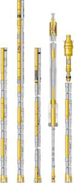
Beyond the bit, there is no "one size fits all" solution to the equipment used in a liner drilling application. Rather, the system should mirror the needs of the well, and the tools deployed depend on the complexity of the wellbore, and the geometry and geology of the reservoir. If a vertical well is to be drilled without the need for building angle, steering, or logging, a simple hydraulic balance liner drilling system can consist of a liner setting sleeve, Type I landing collar, float collar, and casing drill shoe. This is a robust system, capable of operating at higher revolutions per minute (RPMs) and for longer times down hole. However, this option does not include a top packer or liner hanger, which places an upper limit on pumping rates and circulating pressures.
When drilling into sections where higher circulation rates and pressure spikes may lead to lost circulation, the liner drilling system may be equipped with a top packer and liner hanger assembly. A liner drilling assembly that incorporates Baker Hughes' TORXS hydraulic balance expandable liner hanger system, for example, affords higher RPMs of the drill bit in combination with an expandable hanger system that allows for higher circulating pressures, better handling of pressure spikes, and a cleaner wellbore while drilling. The system incorporates ZX expandable seals to provide reliable top sealing and one-trip, two-stage setting without a plug bump. Additionally, the bypass area is another key element of liner drilling system, which allows better cleaning with improved circulation pressure.
Higher RPMs not only shorten the time required to drill the section, but also improve subsequent cementing operations. Faster rotation of the bit assures more efficient drilling through potential trouble zones to provide a wellbore with a straight and smooth profile. Higher revolutions also create smaller cuttings in a narrower size distribution for more efficient circulation out of the hole and a cleaner wellbore resulting in better cement bonding.
For other liner drilling applications, the well may require additional reservoir information through logging, which can be used to adjust the well path. This requires additional hardware on the liner assembly.
The SureTrak steerable drilling liner is one option. It incorporates a rotary steerable system with modular logging-while-drilling and measurement-while-drilling systems. This service acquires various real-time wellbore datasets, including pressure, resistivity, gamma, neutron and density, which allow the rotary steerable system to drill continuously and change direction without slowing.
The choice of which type of liner drilling system to deploy depends upon the well's requirements, and must also account for the added risks associated with more sophisticated assemblies, and the extra costs. For example, the steerable drilling liner service option may be cost prohibitive for a liner drilling application in a vertical or deviated section of the well (where steering or logging is not required), so the driller may decide to deploy the expandable liner hanger system instead. If the liner section is shorter and deployment of the expandable liner becomes too expensive, the driller may decide to run a simpler assembly with no top packer or liner hanger.
Case studies
Such a project management philosophy was instrumental in the planning and executing of a liner drilling operation in the UK sector of the North Sea. The reservoir conditions for this well included a complex lithology consisting of two unstable cap rock formations, shales, depleted sands, and clay stones in which wellbore swelling and stuck pipe events were highly probable with conventional drilling. In addition, the presence of a fault at a depth of 16,775 ft (5,113 m) raised the risk of complete lost circulation, without the opportunity to drill another section below. These risks prompted the operator to seriously consider P&A the well.
As an alternative, the operator approached the possibility of deploying liner drilling to drill through the trouble zones and get the well to total depth. Because the operator was working on a very tight timetable, the liner drilling solution had to be developed and deployed within a two-week window.
A project management team of UK-based personnel from both the operator and the service company, as well as a Houston-based subject matter expert and support personnel met regularly via conference calls to analyze the well and develop the necessary liner drilling equipment and process. The team settled on a simple liner drilling assembly consisting of a liner setting sleeve, Type I landing collar, float collar, and EZCase casing drill shoe.
To minimize fluid loss while drilling, the "smear effect" or "plastering effect" was considered. This theory is based on the solids created during the drilling operation that are ground into smaller more homogeneous solids, and are then plugged into the narrow lost circulation zones as they travel up the wellbore. No pressure control or lost circulation events were recorded during drilling, which indicated that the combined effect of plastering, stress cage, and MPD technology in the drilling mud worked as planned.
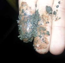
In addition, rotating the liner during drilling likely resulted in the "smear effect," in which the cuttings were pulverized in the narrow annular space as they traveled up the well. These particles become embedded in, or smeared against, the wellbore wall to form an impermeable seal that prevents loss of drilling fluids to the formation.
Additionally, the team used engineering services to develop a drilling mud that incorporated additives to prop open and seal any fractures (per the so-called "stress cage" effect). The team also decided to deploy managed pressure drilling (MPD) techniques through these trouble zones as an additional pressure control and fluid loss mitigation measure.
The next step was to develop a high-efficiency, low-risk liner drilling running procedure. A number of drilling simulations were conducted using actual field data to see how changes to drilling rotation, rate of penetration, fluid circulation rates/pressure, and mud density would impact the safety and reliability of the liner drilling operation.
The next step was to assemble the necessary equipment for the job. The right people were needed on location to perform the job in a short time period. This required combining local expertise in drilling engineering with support from Houston-based subject matter experts. This was accomplished using the service provider's BEACON real-time collaboration centers, which allowed for remote monitoring, support, and control.
With the drilling plan in place and with the collaboration center providing real-time monitoring and communication, liner drilling commenced. A total of 225 ft (69 m) was drilled with liner through the clay stone, shale, depleted sand and two-cap rock seals, and the well reached the planned TD of 16,864 ft (5,140 m) without incident in two days.
Ultimately, liner drilling saved the operator on its well costs and delivered a productive well that would otherwise have been abandoned.
Careful planning was also critical for a liner drilling job in a highly deviated well offshore Mexico. The operator was expecting total lost circulation at a window located at 2,600 ft (800 m) MD while drilling at a 64° deviation. The total length of liner required was 8,860 ft (2,700 m), making this one of the longest liner drilling jobs to date.
The operator and service provider worked together to develop the drilling plan, which consisted of running a 7-in. expandable liner hanger with a liner-mounted drill bit. To minimize lost circulation in the window, an oil-base mud was used.
The system demonstrated high torque capabilities and a better bypass area, combined with a bit that efficiently drilled through the trouble zone. While the original liner drilling target length was 66 ft (20 m), the system drilled 243 ft (74 m), all while maintaining the required 64° angle.
Drilling went according to plan, allowing the operator to reach total depth with no NPT, no fishing or stuck pipe events, and with minimal fluid losses. The operator was able to maintain the planned well deviation and drill this record-setting liner drilling job in one trip. During this job, neither MPD nor seal particles were used, proving that the plastering effect alone helped to mitigate mud loss as a solution for trouble zone solutions.
These are two examples of successful stories realized with liner drilling systems in offshore wells around the world. As wells go deeper and new reservoir challenges arise, the same careful collaborative approach to liner drilling planning and execution will likely lead to similar success.
