PIPELINE MAINTENANCE: Magnetic leakage detection used to spot, measure pipeline cracks
Magnetic flux leakage (MFL) inspection is the most commonly used tech-nology for the inspection of in-service pressurized pipelines. It is estimated that about 80% of line inspection missions are carried out using this technique. The technique is robust and reliable, and advances over the last 25 years have resulted in high resolution inspection systems that achieve accurate and repeatable measurement of defects in the pipeline. High quality inspection can be achieved with minimal disruption to daily operations.
The traditional use of MFL technology has been the detection and measurement of metal loss defects, primarily corrosion, and this is the inspection mission for which the technology is best known. What is less well known is that high resolution MFL technology can be used and adapted for the location and measurement of cracks in the pipeline, in circumferential and longitudinal directions.
Principles of inspection
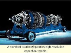
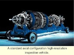
The basic physics of the technique are very well known. The pipe-wall is magnetized axially by a pair of magnet and bristle rings at each end of the magnetizer vehicle. Any disruption to the flow of magnetic field in the pipeline steel, as caused by metal loss in the wall, will cause disruption to and leakage of the field. It is this leakage that is detected and measured by the sensors on board the inspection vehicle.
The axial configuration was initially chosen as the most practical engineering solution and because this configuration enabled the inspection vendor to detect and measure those defects that most commonly occurred in pipelines and were of the most concern to pipeline operators. There are some shortcomings in this technique when looking for defects that have a more longitudinal component. These shortcomings can be addressed by altering the magnetic configuration of the inspection vehicle.
Circumferential cracking
The most common form of circumferentially aligned crack-like defect occurs within the girth weld. Girth weld defects, introduced during construction, can include incomplete weld passes, stop-start, unauthorized weld repairs, and cracking caused by inadequate heat treatment of the weld area.
As these defects are circumferentially aligned, and therefore at right angles to the flow of magnetic flux, they can cause a disruption and leakage of the field that is readily detected. However, the fact that these defects by their very nature are within a girth weld, poses significant technical challenges.
The girth weld itself presents a barrier to axial flux flow, causing a large disturbance to the signal, which can mask defects within the weld. In addition, and perhaps more significantly, the protrusion of the weld bead into the pipeline bore can cause the MFL sensors to "lift off" the inside of the pipe wall.
If the vehicle is traveling at normal pipeline speeds and the sensor design has high inertia, then a dead zone can be created both at the girth weld and for some distance downstream of the girth weld. This means that inspection vehicles cannot detect defects within the girth weld, and indeed for some distance beyond it. In some cases, this non inspected dead zone can be as much as 200 mm.
When a high resolution inspection vehicle was first developed by PII in the mid-1970s, these shortcomings in available technologies were recognized. The initial specification of the vehicle performance required that 100% of the pipeline be reliably inspected, including the girth weld and the area around it. So care was taken at the very start of the project to ensure that full inspection capability was not compromised by the presence of the girth weld.
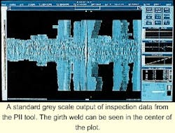
The first problem, that of the large and sometimes confused signal generated by the weld, was tackled by using the very high magnetic field of the PII tool (necessary to saturate the pipe wall and generate repeatable signals from small defects). This, coupled with the very high sensor density of the high-resolution tool, means that the signal from normal girth welds is remarkably repeatable, and any abnormality in the weld can be easily identified.
Designing the sensor heads themselves to have very low mass solved the more serious problem of sensor lift-off. This design, coupled with very light spring suspension, means that the sensor carrier has low inertia and 'bends' with the weld bead, traveling over it smoothly rather than bouncing off the pipe wall.
The fact that all girth weld anomalies are by definition very short in the axial direction can pose problems for the analyst. It can be difficult to discriminate between the various types of defects that can occur in girth welds. The solution lies in the experience and training of data analysts. The first girth weld crack was identified and confirmed in the early 1980s. Since that time, we have located and confirmed more than 1,000 girth weld cracks in operational pipelines.
Longitudinal cracking
The extent of the flux leakage created by a pipe wall anomaly, and therefore the size of the signal collected by the in-line inspection device, is affected by the width of the anomaly. A circumferentially wide defect will set up greater opposition to the flux induced by the tool, and a larger signal will result.
The reverse also holds true. As a longitudinally aligned defect becomes narrower, its opposition to flux flow diminishes, and the resultant signal will decrease in magnitude. The extreme of this phenomenon is demonstrated by the fact that longitudinally aligned cracks cannot be detected using conventional magnetic flux leakage technology.
The result is that with inspection devices carrying only a few MFL sensors, a longitudinally aligned defect will not be detected. With high-resolution tools the high sensor density enables the defect to be detected, but the reduction of the signal strength can lead to an underestimation of the size of the defect.
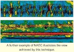
The defects that have been recognized as present in some pipelines and designated as narrow axial external corrosion (NAEC) are very rare in PII's experience, as they are not only narrow but are longitudinally orientated, axially long and relatively smooth in profile.
Following the discovery of NAEC on one particular pipeline, the data from the previous MFL inspections of that line was examined closely by a PII-client team. Although it was confirmed that the inspection tool had collected data from these defects, the level of signal was such that the depth of the NAEC had indeed been underestimated.
An attempt was made to create algorithms that would recognize the character of NAEC, and correct the sizing model to compensate for the problem and predict depth more accurately. This project met with some limited success, but was found not to be 100% reliable for the purpose of establishing confidence in the condition of the pipeline, given the extent of the NAEC phenomenon.
Transverse field inspection
If metal loss that is long and narrow will not produce signal strengths compatible with accurate sizing when the magnetic field is longitudinal, then another approach is to magnetize the defect in the orthogonal direction. This means that a tool had to be devised and constructed that would magnetize the pipe in the circumferential direction.
Theoretically, this means that the signal obtained will be far more prominent and will allow more accurate characterization. In addition, the axial extent of the defect should be clearer.
The idea of applying the magnetic field in the transverse direction is not new. AMF (formerly American Machine and Foundry) was probably the first to develop the idea as part of their mill inspection technology in the 1960-1970 period and patented a rotating transverse field system in 1978.
PII also examined it.
The reason these designs and prototypes never came to fruition was due to a limitation of the technology available at the time, rather than in the technique itself. Data in the 1970s was usually stored on reel-to-reel recorders, and displayed on UV sensitive paper. Given the advances in computing techniques, materials science, and electronics since then, confidence that a solution for the problem of long narrow defects could be achieved was high. However, without a commercial impetus, the technique was probably destined for obscurity. The discovery of NAEC and several long seam defect failures in North America provided the impetus to develop a commercially viable inspection system. A prototype, dubbed the Transcan tool was designed, constructed, and launched within a five week period and collected good quality data on its first inspection run of more than 200 km.
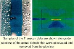
Analysis of the data and subsequent excavation revealed that the tool did provide an improved characterization of NAEC. This was particularly promising when considering that both the tool and the analysis technique were first attempts. The short times cales available for right-of-way access meant that only a limited amount of information could be gathered from field excavations, but the wealth of data obtained from the excavations carried out in 1996 means that extensive detailed correlation is possible.
Hook cracking
Encouraged by this success, PII refined the process still further to build an in-line inspection tool that would reliably detect and characterize long seam defects. This work was encouraged by one client who had experienced operational failures caused by hook-cracking in a 20-in. crude oil pipeline.
Defects, such as hook cracks and lack of fusion, have caused many in-service and hydrotest failures, especially in liquid lines subject to pressure cycling. Hook cracks occur when inclusions at the plate edge are turned out of the plane of the steel during the pipe manufacturing and welding process. These may pass the initial hydrotest, but fail later through fatigue-induced cracking. It is the turning out of the metal at the weld which gives the crack its characteristic "hook" or "J" shaped appearance.
Although such defects can be det-ected by manual non-destructive testing (NDT) methods, they have remained largely outside the domain of automated methods and in-line tools, which are used for the mass inspection of pipelines. Until recently, the only option was to hydrotest the line. This has limitations in as much as it gives an "all or nothing" or "yes/no" indication. It is not a quantitative technique.
Severe defects are identified through failure, but no information is conveyed about less significant defects which may themselves grow to criticality within a short time after the test. To ensure these defects are found, repeated testing at frequent intervals is required. In addition, following a hydrotest where there has been a failure, the line must be repaired and hydrotested repeatedly until there are no more failures. This is costly in terms of effort and lost throughput.
In this case, the service failures experienced in this 1500-km-long, 20-in. pipeline had resulted in a significant reduction in throughput for the pipeline, with subsequent loss in revenue, and a regulatory requirement to hydrotest the entire pipeline, at a projected cost of tens of millions of dollars.
In the spring of 1998, PII developed a high-resolution 20-in. Transcan tool carrying 400 primary sensors, which was laboratory tested and used to inspect 140 miles of 20-in. pipeline. The tool was successful. In order to validate the technology, the client excavated the reported defects and repaired and hyrotested the line. Two separate sections of the line, totaling 118 miles, were hydrotested to 125% MOP without failures.
More than 50 hook-cracks were detected by the tool and validated by "in the ditch" NDE. The smallest was 5-10% of pipe-wall thickness (Fig 11 and 12). In addition, many examples of lack of fusion and stitching, and three examples of cracks within dents were detected. Only two of the cracks verified would have failed a hydrotest at 125% MOP. The hydrotest requirement was lifted and following the inspection and repair of the remainder of the 1500-km line, full operating pressure was restored.
During the course of the remaining inspection, many hundreds of long-seam defects were revealed and repaired.
The Transcan has been used to inspect over 4,000 km of pipeline, and plans are to extend the range up to 42 in. and down to 8-in., with a 6-in. tool being a distinct possibility in the future.
Stress corrosion cracking
Given its sensitivity to axial features, would TFI be able to detect stress corrosion cracking? Recent work on behalf of the operator of a refined products line has shown some initial promise. Specifications of the line are seamless, 12-in. in diameter, 100 km in length, wall thickness of 6.35-7 mm X52 & X60 grade steel, and is 30 years old.
The pipeline had suffered from several failures due to stress corrosion cracking (SCC) and regulatory authorities required that the operating pressure be reduced from 90 bar to 60 bar and a program of hydrotesting be implemented. To investigate the capability of detecting SCC, a test program was undertaken on samples of defective pipe.
In parallel, a 12-in TFI tool was prepared for a trial run in the pipeline. The results from this run have been analyzed, and reporting will be followed up by proving excavations. The laboratory tests showed that it was possible to observe some colonies of SCC using the Transcan technique. However, as always, the true test is in the ability to discriminate these signals from other features in the line, such as manufacturing variations, corrosion sites, surface roughness, etc.
In parallel with this investigative inspection program, extensive testing was carried out on the Transcan tool using known colonies of SCC installed in a pull through string. TFI is not intended to be a primary inspection tool for SCC (ultrasonic tools probably offer the best performance here), but any success in this area is regarded as a bonus on top of its capability at inspection for axial metal loss features and defects in long seam welds.
Third party damage
During the inspection and subsequent repair of the 20-in. pipeline described previously, several instances of third party damage were located and confirmed. - Shown is an instance of third party damage uncovered on this pipeline.
As third party damage is the largest cause of pipeline failure in most countries, we feel that the technology has potential to allow pipeline operators to not only detect, but also characterize these kinds of defects. A development program has begun in the US with the Battelle Institute, the Gas Research Institute, and the Office of Pipeline Safety. This program should allow the development of a system for accurate location, identification, and characterization of this difficult-to-detect defect.
Crack-like defects in operating pipelines have long been the most difficult defect to locate using in-line inspection techniques. For many years, the pipeline industry has had to rely on the inexact science of hydrotesting to mitigate risk from failure due to cracking. New tools are superior to hydrotesting, technically and financially. ;
Acknowlegement
A slightly longer version with more illustrations was presented at the PII 5th Annual Pipeline and Pigging conference in Seville, Spain.
References
J. F. Keifner, "Installed pipe, especially pre-1970, plagued by problems", Oil and Gas Journal, pp 45-51, Aug 10, 1992.
API Bulletin on Imperfection Terminology (5T1), 9th edition, May 31, 1988.
R. D. Barton, US Patent 4072894, Rotating Pipeline Inspection Apparatus, 1978.
E. M. Holden, "Transverse Field - a new direction for inspection," Venezuelan Pipeline Conference 1999.
J. F. Kiefner, "Pressure Management Key to Problematic ERW Pipe", Oil and Gas Journal, pp 80-81, Aug 17, 1992.
P. Mundell, K. Grimes, "A new breed of intelligent pig for the detection of defects in the long seam weld of steel pipelines", Journal of the British Institute of NDT, Vol41, No2, February 1999.