Advanced Technology
UK group developing program to assess jacket joint cracking
Does a cracked platform jacket tubular joint provide enough strength remaining to withstand certain static or dynamic conditions? How long can an operator leave a cracked tubular in service before replacing or strengthening it?
These questions have long troubled operators. There has been no lack of understanding in design sufficiency in structurally sound platforms, but little is known of what happens once cracking begins.
The Offshore Safety Group of the UK Health and Safety Executive is developing a software program that will safely predict the risks, particularly that of static loads, involved in cracked joints. The program is expected to incorporate the following:
- A failure assessment diagram to assess crack conditions.
- A non-linear finite element analysis investigation of a range of crack and uncreacked tubular joint geometries.
Four fully instrumented tests on large scale joints will be conducted, duplicating the finite element analyses. The first test was carried out in January of this year and the project is scheduled to conclude in mid or late summer.
Shell program allows well spacing for gravity drainage
A Shell Canada program developed for bitumen recovery through gravity drainage in parallel horizontal wells in Canada can be used successfully in crude drainage wells in partially depleted reservoirs offshore.
The directional surveying technique involves the use of a measurement-while-drilling (MWD) unit in the second well to detect the magnetized casing in the first well without intervention in the first well. The program was successful at separation distances as large as 65 meters, but could be extended with additional equipment development.
According to Shell's group engineers, conventional surveying techniques could not meet the required 10 meter lateral and 2 meter vertical directional tolerances to maintain the ideal separation in the Canadian well. Casing in the first well disturbs the earth's magnetic field, a component in azimuth measurement.
The Shell method involves magnetizing the casing in the first well with an alternating pole pattern before running it in the hole. After that, a conventional MWD could be used to measure local earth response and casing response every five meters.
Off-the-shelf package bringing remoteimaging costs down
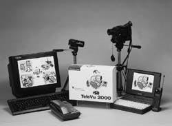
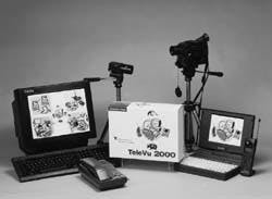
Simultaneous video, text, and voice transmission over a standard telephone line anywhere in the world using standard personal computers and cameras has now cracked the $1,000 cost barrier. The first software packages to accommodate the process are now available.
Until now, most remote video packages were customized for customers, usually manufacturers that needed to support engineering representatives in the field, and required special equipment at high cost. Even more expensive was a second alternative, videoconferencing, which also required special equipment and special telephone lines.
Unet TeleVu of Richardson, Texas is among the latest packagers of communications packages to meet this critical field need. One telephone connection will handle voice, data, and images, allowing for transmission of images without interrupting voice transmission. The images are captured from any type of digital camera equipment.
Field personnel will only need to carry a PC with modem, camera, and camcorder to remote locations to carry out the interactive conferencing. A bridging device accompanying the software allows access to local area or wide area networks. The software also has a remote polling function that allows the transfer of data and/or images periodically from remote sites with intervention.
Unet TeleVu, a remote simultaneous image and voice transmission software package, uses off-the-shelf hardware.
EM tomography effective in between-well probes
A high power, low frequency electrical resistivity system developed by US national laboratories can effectively probe the contents of pore spaces between wellbores at distances up to one kilometer.
The pore space information produced by the system complements seismic data, which tends to measure broader geological factors. Some types of shear seismic are able to produce pore space information, particularly in gas reservoirs, but the technology is still being developed.
The resistivity system was developed in Lawrence Berkeley and Lawrence Livermore national labs in California, and was used originally at frequencies above 20 megahertz to detect tunnels and underground faults vital to military objectives.
While the original system worked well in rocks and other dense formations, it lacked the power to penetrate soft rocks and loose formations. So developers, assisted by Schlumberger and Sandia National Laboratory, dropped the frequency to the single kilohertz range and boosted the power to gain penetration distance. Much of the equipment development is still underway and no commercial systems have yet been introduced.
The technology is important not only in determining interwell heterogeneity and mapping reservoir properties, but also in measuring frontal changes in enhanced recovery.
Resistivity in underground formations depends on pore fluids and degree of saturation in pore spaces. The analog system consists of a transmitter attached to the borehole wall in one well and a receiver installed in another, not unlike borehole seismic systems.
The frequency of the transmission must be varied according to well spacing and background resistivity. When the frequency is too low, the resolution drops off. At too high a frequency, the reception qualify drops unless the range is short.
Both the transmitter and receivers have separate power sources, a common grounding, and are connected by cables. In multiple holes, the receiver remains stationary, and the transmitter is moved. Depth intervals are 100-200 meters.
The resistivity distributions between the various holes are recorded and a least squares inversion technique is applied to develop a useful geological and pore space model. Converting the model into a full 3D display is difficult and will require more work and certainly more computer power.
In a California steam flood project featuring testing of the resistivity equipment, it was found that higher resistivity intervals respresented oil sands and lower resisitivity indications were shales, silts, and other confining barriers. Borehole logs verified the data derived from the system. Shifts in the steam flood fronts were visible in a model developed over time.
Another interesting factor in the resistivity system is that variations is water salinity in the reservoir show up easily. Resistivity is a function of water salinity. In water floor projects, injected water, when it varies from ground water, can be detected by the system in measuring frontal change.
Copyright 1995 Offshore. All Rights Reserved.

