WELL TESTING Vessel tests and processes high flow volumes on critical wells
Ray Bullock
Halliburton Energy Services
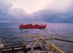
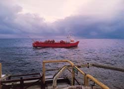
The M/V Crystal Sea stands off a platform in preparation for well testing.
Offshore operators can apply fluid/gas/solids separation technology, sea-going capability, analytical capability, and at-sea storage to avoid oil flaring during well testing. In the first application of its kind, the well test vessel M/V Crystal Sea combines advanced process technology to receive waste products and crude oil from fixed and floating offshore installations during well testing.
Traditionally, test fluids are flared to the atmosphere. The well test vessel (WTV), which is a result of a joint venture between Halliburton and Brovig Offshore, incorporates a processing plant that captures oil and gas normally flared during the testing operations. The tests are usually performed to determine the size, viability, and optimum production capabilities of a field under exploration. This processing plant is capable of salvaging products from the well and processing the oil to refinery standards. The WTV reduces the potentially harmful effects of well testing to the environment while enhancing the overall financial efficiency of the well testing operation.
Technology
The WTV is a dynamically positioned ship equipped with processing equipment to separate water, residuals, solids, and some gas from the crude oil. The stabilized crude can then be stored in cargo tanks, transported and discharged to oil terminals.
The WTV allows higher flow rates than can normally be achieved using conventional rig-mounted well test equipment. This increased throughput capacity of the onboard plant reduces heat radiation normally generated by an oil flare. The WTV can process up to 4,000 cu meters/day of fluids (or more, subject to fluid characteristics) and can flare up to 300,000 cu meters/day of gas.
In addition to avoiding potential carbon dioxide penalty taxes and cleanup costs, operators may, in many cases, be able to offset the cost of the testing service through revenue brought in by selling the captured crude. The 8,000 cu meters storage capacity of the vessel also allows more extended tests to be performed at higher flow rates than would be possible on a rig operating without the WTV.
Because the vessel results in more environmentally friendly testing, government approvals for the startup time for tests in more sensitive areas could be substantially reduced. The vessel's utilities and process equipment having undergone a full environmental review and design assessment, are equipped to comply with the current legislative framework and to minimize, where possible, any environmental impacts.
The only emission from the WTV into the environment is from production or drainage water, gas flaring and engine exhaust. The WTV carries water cleanup equipment in the form of hydrocyclones, a downstream enhancement vessel, and polishing filter package capable of cleaning water effluent streams to well below the 15 ppm limit set by MARPOL Shipping Regulations. The system will also alert the crew immediately and automatically divert flow to slop tanks if this limit has been exceeded. Oily sludge, shipboard waste, and sewage are retained onboard and disposed of by the appropriate means when the vessel is docked.
Applications
The WTV is designed for the following applications:
- Conventional well testing and cleanup using state-of-the-art production testing equipment.
- Extended well test and early production when coupled with a shuttle tanker and connected directly to a subsea tree through a flexible pipeline. This setup allows early release of the drilling rig and can continue well testing or early production, which results in more timely economic returns to the operator.
- Tanker capabilities as a fully coded crude oil tanker. The WTV is well suited as a parcel-product carrier. The pumping capacity can discharge a full cargo in 6 hours.
- Oil recovery in cases of major disasters, such as blowouts. The WTV can serve as a recipient of oil/water emulsions from the oil recovery vessels at work. The WTV can hold up to 8,000 cu meters, compared to 1000 cu meters for a standard oil-recovery vessel.
- Support vessel in rescue operations. The small size of the WTV combined with its maneuverability allows oil transfer operations close to stranded vessels or other objects representing a pollution threat.
- Coiled tubing and wireline operations. The moonpool configuration and DP classification enables the vessel to be used in intervention services, although some alterations and additions to deck facilities would be required.
System Operation
Well fluids are normally a mixture of hydrocarbons, water, and solids. The hydrocarbons range from heavy, viscous crudes to low-volatility crudes with a high proportion of gas. The water content normally ranges from 0% to 80%. The WTV processing system is designed to cover this wide range of production conditions. The fluid processing procedures occur in the following order:
- Well fluids pass through a wellhead choke and are routed to the WTV through a quick-connection/disconnection (QCDC) skid mounted on the rig, and a 6-in. ID flexible pipeline. Fluids can also be routed first through the rig-mounted test separator, where Stage 1 separation can take place.
- Stage 1 gas is sent to the rig flare system, while the oil and water are recombined upstream of the QCDC skid.
- Well production fluids first enter the slug catcher, which performs two-phase bulk gas separation and smoothes the flow of liquid. A pressure-control valve maintains pressure by discharging gas as required to the flare system.
- The gas stream normally flows through a separator to remove droplets of liquid carried over from the vessel. Liquids flow to the pre-separator hydrocyclones through either a control valve or the booster pumps that react to the influence of the slug catcher level controller. Inert gas may be supplied to maintain the vessel pressure if the gas evolution from the liquids is low.
- The pre-separation hydrocyclones perform bulk separation of water and oil. The ratio of differential pressure between the inlet and each of the outlet streams is adjusted so that the stream flowing to the Stage 1 oil separator is mainly oil and the stream flowing to the Stage 1 water separator is mainly water.
- The Stage 1 oil separator performs three-phase separation. Sufficient pressure is maintained within the vessel to enable oil to be discharged to the Stage 2 separator and water to the stage-one water separator. These streams are discharged through control valves that are regulated by the relevant interface level controller. Pressure is maintained by a pressure-control valve that discharges gas to the flare system, as required. If gas evolution from the fluids is insufficient to allow proper level control, inert gas may be supplied to maintain the vessel's pressure.
- The Stage 1 water separator performs like the Stage 1 oil separator except that the water stream is discharged to the de-oiling hydrocyclones.
- Oil from both Stage 1 separators flows to the Stage 2 separator through the crude oil heater. The heater controls the temperature in the Stage 2 separator to enhance separation and to ensure the required Reid vapor pressure (RVP) of 11 psi at 37C is achieved.
- The Stage 2 separator also performs three-phase separation. Oil containing not more than 5% water is discharged to storage by the oil transfer pumps through a control valve that is regulated by the separator oil-level controller and the oil cooler. Water is discharged to the Stage 1 water separator by the water recycle pumps through a control valve that acts under the influence of the separator water-level controller. The vessel is connected to the flare system through an open vent.
- The flare knockout drum receives gas from the slug catcher, both Stage 1 separators, and the Stage 2 separator. Gas is discharged to flare, and liquids are pumped back to the Stage 2 separator under level control.
- Water from the Stage 1 water separator is routed to the de-oiling hydrocyclones, which return oil and some water to the inlet of the heater while discharging water to a downstream enhancement vessel.
- The downstream enhancement vessel performs final degassing of the water, which also enhances the oil/water separation process. The vessel is connected to the flare system though an open vent. Water from the vessel is expected to contain less than 40 ppm of oil and discharges to the ship's system directly or through a pair of filters that perform final polishing. An online analyzer measures the free-oil content of the produced water and can measure oil-droplet sizes of 2 microns to 300 microns. The analysis ranges from 2,000 ppm to 10 ppm.
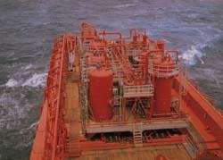
Processing plant tank, equipment, and piping runs are shown on the deck of the M/V Crystal Sea.
Computer-based controls
The WTV processing package is controlled through a dual-monitor computer system. Data acquisition and performance monitoring are carried out by the computer-based control system. This system allows any variable to be recorded against a time base. Data may then be recalled for trending and analysis. As a minimum, the following parameters are continually monitored, totaled (where appropriate), and recorded:
- Corrected gas flowrate to the flare
- Corrected crude oil flowrate to storage
- Water content of the crude oil flowing to storage
- Water flowrate to overboard dump/slops tank
- Oil content of water flowing to overboard dump/slops tank
Emergency shutdown
The emergency shutdown (ESD) system is independent of the control system and comprises fail-safe logic cards to perform process and emergency shutdown operation. The objectives of the ESD system are as follows: protection of personnel; protection and operational safety of equipment; and minimization of environmental pollution
The principles of operation are based on operational abnormalities that determine shutdown conditions when sensed from individual criteria such as pressure, temperature, or level switches. In addition to automatic shutdown, the operator can also control all or part of the plant.
Mechanical strength as well as instrumentation logic for fail-safe systems are designed into the system to help prevent development of potentially dangerous situations. Additionally, there are emergency shutdown signals that are generated manually from break-glass units, strategically positioned throughout the plant. Signals are also generated by the fire-detection system, the flammable-gas detection system, and the hose-transfer system.
Technology summary
The WTV incorporates a sophisticated package of equipment for well testing that has been designed specifically to meet the rigors of shipboard well-test process applications within the onboard process system:
- A hydro-transportation device that removes solids is incorporated into the slug catcher vessel. Developed primarily for use in the mining industry, where the need for efficient slurry pumping is essential, the unit provides a means of online or batch removal of well-testing solids (produced sand, rathole solids, frac sand, proppant, etc.) from a containment area inside the slug catcher vessel. Dual units remove solids from within the slug catcher and transport them to a slops tank aboard the WTV for later cleaning and disposal onshore.
- Pre-separation hydrocyclones, placed directly downstream of the slug catcher, burn pressure while achieving bulk oil/water separation in a manner that coalesces the remaining oil droplets in the produced water rather than subjecting them to the shear forces normally encountered in control valves. The pre-separators, with no moving parts, are insensitive to motion-produced, high internal G forces.
- A high-efficiency separator for removing liquids and solids from gas is used to dry gas streams before recompression or flaring. Adapted from the Russian oil industry, the unit captures and removes entrained fluids carried over in the gas stream from the slug catcher and returns them to the oil train for process and storage. The unit is insensitive to motion, has virtually no pressure drop across the unit, and reduces the need to inject methanol to manage hydrate formation.
- Motion-compensated gravity separators use many innovations to calm fluid motions encountered when operating processing facilities aboard a moving vessel. Calming tubes are used to contain level-sensing devices, and sophisticated vane packages, circumferentially inserted, help eliminate spaces to still fluid waves and surges.
- A produced-water treatment system uses a combination of de-oiling hydrocyclones, downstream enhancement vessel, and an automatic, coalescing filter that can be backwashed to recycle produced water, enhances water cleanliness to a level of 15 ppm (or less) free oil in water. The system is designed to allow inclusion of membrane technology which has the capability of further reducing the free-oil levels to 5 ppm when needed. This unique combination of process equipment is responsible for the capability of the WTV to treat produced and oily waters to attain water cleanliness levels that permit its disposal into the sea.
An online analyzer uses "time of transition laser particle and oil droplet size" technology to monitor discharge condition of processed water. The processed water is continuously monitored, and water that does not meet specifications is automatically routed to holding tanks for onboard storage and further treatment before discharge.
References:
Ashwell, C., Bringsli, S., Bullock, R., and Taylor, R.W.: "The Well Testing Vessel "APTV": Cost Effective Alternative to Flaring Hydrocarbon into the Atmosphere," paper presented at the ASME Energy & Environmental Expo 95, Offshore & Arctic Operations Symposium, Houston, Texas.
Tjelta, O., Ashwell, C., Hilmarsen, G., and Taylor, R.W.: "Offshore Northern Sea Case Histories of the Environmentally Friendly Testing Vessel, the "APTV," paper OTC 7684 presented at the 1995 Offshore Technology Conference.
3. MARPOL: International Convention for the Prevention of Pollution from Ships 1997 and the Related Protocol of 1978.
Author
Ray Bullock is the operations manager for the WTV M/V Crystal Sea. He joined Halliburton (Otis) in 1973 and has 20 years of well testing experience. He has held management positions in the UK, Norway, Bahrain, Dubai, Iran, Abu Dhabi, Oman, Nigeria, Canada, The Netherlands, and the US.
Copyright 1995 Offshore. All Rights Reserved.


