Platelets seek, seal line leaks
Managing pipeline integrity is crucial. High commodity prices mean that the financial implications of an unplanned production shutdown can be substantial. In addition, potential loss of life and censure from the growing environmental lobby can result in severe non-financial implications.
Traditional methods of locating and sealing leaks require divers or ROVs for installation and require direct access to the leak. This can prove to be expensive and time consuming when pipelines are long, buried or otherwise inaccessible. Umbilicals or bundled pipelines add to this difficulty as the eventual point of fluid egress can be some distance from the actual site of the internal line leak.
Brinker Technology’s Platelet Technology is a novel approach to leak location and sealing in pressurized pipelines. Discrete particles, known as “platelets”, are deployed into a pipeline and use fluid flow to carry them to the leak site. On reaching the site, fluid forces entrain the platelets into the leak where they are held against the pipe wall to stem the leak. Development of a platelet solution uses an engineering process that includes analytical and numerical modeling, physical testing, and material compatibility analysis.
Platelet Technology also offers operators leak location by incorporating a traceable tracking device, generally a radioactive source, into each platelet. These platelets are deployed as normal, but would be detectable from injection through to entrainment. A radiation detector can be mounted in an ROV or carried by a pig to accurately locate the Platelet that is providing the seal. The seal is formed inside the pipeline at the exact location of the leak. This prevents any confusion as to the location of the leak as in umbilicals or bundled pipelines.
Platelet Technology generally can apply where there is flow in the line and a positive pressure differential acting across the pipe wall. Platelets could be used to seal leaks in small bore subsea umbilicals operating at 500 bar (7,252 psi) but are equally able to seal leaks in large pipelines operating at just above atmospheric pressure. From its first deployment in a water injection line in BP’s Foinaven field in 2004, Platelet Technology has continued to improve and evolve and is being optimized for use in hydrocarbon lines, gas lines, flexible flowlines, and downhole applications.
As an engineered solution, the platelets are matched to each situation and take in to account the temperature, pressure, and how aggressive the fluid is in each case.
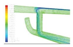
Development for a platelet solution involves a systematic scheme of numerical modeling and physical testing. Computational Fluid Dynamics (CFD) analyzes fluid flow within the pipeline to determine platelet behavior within the leaking line. This analysis has two parts: modeling of platelet conveyance through the system infrastructure to ensure they reach the leak site without obstruction, and simulation of platelet behavior in the immediate vicinity of the leak to assess platelet entrainment. CFD simulation is vital to develop a solution as it allows the platelet density to be tuned for a high entrainment probability with a minimum number of platelets. Generally, platelets are designed to be neutrally buoyant in the carrier fluid. Turbulent flow within the pipeline is used to ensure an even distribution across the pipe cross section. If the platelets are too heavy, they sink to the bottom of the pipeline. If they are too light, they float to the top. Either can result in an uneven distribution. However, this can be altered if circumstances require. For instance, platelets can be made slightly heavier to increase the likelihood of them finding the leak on the bottom of the pipe.
From the output of the CFD analysis, a high-pressure flow loop gives “real life” assurance of the platelet design. A flow loop that is representative of the pipeline system (and the defect within it) can be set up and simulation of the operation conducted. While this is not required in every case (as CFD can often give enough information), more complex leakage situations often justify physical testing.
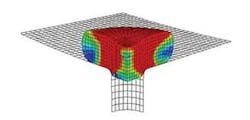
The second facet to the design process is to ensure that the platelets meet the seal integrity and longevity requirements. Material selection is important as the platelets must be compatible with the fluid in the pipeline. To analyze performance of the platelet seal, numerical modeling, physical testing, and material compatibility analyses are used. Third-party analysis determines the change in the platelet material properties (such as creep) as they age in contact with the pipeline fluid under temperature. The information from extended life testing can be used in a Finite Element Analysis (FEA) model to analyze platelet seal integrity under load. This allows Brinker Technology to tune the Platelet characteristics to ensure the required seal integrity. As an additional measure, pressure vessel testing is conducted to provide physical assurance that of seal integrity under a range of pressure and temperature conditions, and fluid types.
For all testing, an estimate of the actual leak geometry is used. It may not always be possible to gain knowledge of the exact defect geometry. In many cases there is enough information to estimate the defect size and geometry. Pressure and flow data can determine defect size and operators often have intelligent pigging data that allows defect types to be inferred.
Field implementation
Brinker Technology has conducted several operations for operators such as BP and Shell. The technology is easily transportable and can be used worldwide. Field implementation of a Platelet solution generally does not require specialist equipment. Pig launchers and double block and bleed valves are some of the pipeline elements that can be used as injection points.
Leak sealing is generally a reactive technology only applied when a leak is present. Platelet Technology is applicable proactively when a leak may be imminent.
BP Foinaven field
Foinaven field is around 150 km (93 mi) west of the Shetland Islands in the UKCS in a water depth of 500 m (1,640 ft). A leaking flange on the Foinaven water injection system caused reduced production. The leak was just downstream of a complex pipeline connection, making traditional sealing methods unfavorable. A solution was required to last over the winter period until a planned shutdown in spring 2005 (6-9 months).
To minimize the number of platelets injected, CFD ascertained the behavior of the platelets around the leak. A full-scale flow loop was constructed to physically test performance. The next stage was to design and test the platelet injection system. In this case, a weight loss coupon was used as the injection point.
Located 500 m (1,640 ft) subsea and 800 m (2,625 ft) from the topside injection point, the leak sealing operation was challenging. The design work identified that less than a pint of platelets would require to be injected and BP deemed it acceptable to let the excess platelets pass into the well in this case, as the volume was so low.
Platelet deployment was a success. The leak was sealed within 24 hours from the start of the offshore operation. As a result of the platelet seal, line pressure increased by 20 bar (290 psi) with a consequential increase in water injectivity from 141,000 to 154,000 b/d, which had an immediate impact on reservoir production. BP said the cost of a Platelet solution was approximately 10% of the cost of designing and fitting a clamp to the leak.
Apache Forties field
The Forties field development lies 190 km (118 mi) east northeast of Aberdeen, UK, and consists of five steel structures. Forties Charlie is the central gathering platform that is connected to the Alpha, Bravo, and Delta platforms via 20-in (50.8-cm) diameter oil pipelines originally installed between 1973 and 1975. In 1986, the Forties Echo platform was installed. It is connected to Alpha via a 12-in (30.5-cm) oil pipeline. The Forties field pipelines then feed into the BP-operated export pipeline to Cruden Bay, Scotland.
These four oil pipelines, which vary in length from 3.3 km to 7.6 km (2 mi to 4.7 mi), have passed their original design life and it is timely to prepare a Platelet contingency to minimize any environmental impact and reduce production downtime in the event of a failure.
Results of intelligent pigging runs in the pipelines carried out in the last few years show that the majority of wall thinning due to corrosion lays in the lower section of the pipeline (6 o’clock grooving). However, corrosion is present, albeit to a lower extent, at all positions around the circumference of the pipeline. A Platelet solution will be designed to target leaks at any location.


