New tools and technology for the offshore industry

In-situ pressure control inspection lowers costs
A variety of in-situ inspection and remediation tools have been designed to reduce the amount of time and money required to inspect and repair subsea equipment. NOV’s aim is to lower the total cost of ownership for drilling contractors by reducing the need to transport large assets to a shore-based repair facility.
If equipment fails an in-field inspection, the drilling contractor can weigh the option of replacing equipment or scheduling an in-facility repair to correct the issue. For infield repairs, it is important to note that only a working pressure test is required, removing the need for a dedicated test bunker.
In-situ inspection or remediation tools offered by NOV include:
• BOP bore seal seat machining
• BOP door face machining
• BOP phased array stud inspection tool
• BOP ring groove machining
• Riser UT wall thickness corrosion mapping for auxiliary lines
• Riser UT wall thickness corrosion mapping for main tube
• Riser main tube phased array flange pocket inspection tool
• Riser main tube phased array UT inspection tool
• Riser auxiliary line pulse echo UT inspection tool
• Riser hydraulic seal sub removal tool
• Riser box honing tool
• Riser pin honing tool.
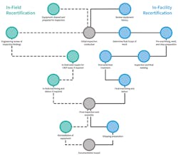
For equipment requiring in-facility repair, care is taken to pre-machine and inspect parts to ensure that satisfactory surface conditions are achieved before beginning the welding or inlay process. All equipment is machined to precise dimension according to NOV engineering prints and then checked by the quality assurance personnel. Documentation is then reviewed by the quality assurance department to verify that all required information has been included in the drilling contractor’s final documentation package.
To ensure drilling contractors’ products are returned to their optimal condition, all inspections are carried out using the latest revisions of the OEM bill of materials and engineering drawings. •
AIMS Global Consulting launches ZynQ 360
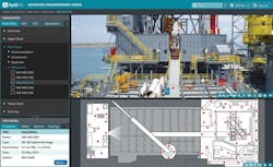
AIMS Global Consulting LLC has launched ZynQ 360, a web-based software solution that utilizes high definition, 360-degree spherical photo and video technologies. The company says that ZynQ 360 complements its asset integrity management services that help clients with regulatory compliance and reduce operational costs and risk on their physical assets.
AIMS says that the software can help users:
• Reduce operation costs, risk, and operational downtime
• Review operations, allowing operators to identify what is most important
• Collaborate with workers on a global scale
• Increase sustainability for engineering and regulatory compliance information
• Obtain ubiquitous access to key asset information
• Comply with regulatory requirements.
“ZynQ 360 enables real-time collaboration and visual review of an asset,” said Robert Smith, Head of Americas for AIMS Global Consulting. “We complement the model by building a bridge between existing systems and users, making information more readily available and easy to extract.” •
Umbilical survey reveals integrity issues with modified buoyancy
Ryan Diver
Jee
Earlier this year, a major international operator commissioned Jee to perform a study on a subsea main control umbilical (MCU). Installed in the 1980s, the unit serviced two subsea control modules via a junction box beneath the client’s floating production vessel (FPV). The study was needed after a recent ROV survey of the MCU identified anomalies with the buoyancy modules.
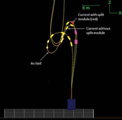
A review of the footage revealed several issues. The first module was missing from the base of the umbilical. The second module had split in half but remained tethered to the MCU, sliding up the line and stopping at the base of the third module, causing both to slide up toward the hog bend. Also, over the hog bend and into the sag bend, the remaining modules had all relocated a few meters from their as-laid positions up toward the hog bend.
To reinstate buoyancy, the client had attached two new modules to the MCU of similar design and positioned both close to the as-laid locations of the detached and split modules. The split module, now made redundant following the addition of two new modules, remained tethered to the MCU.
The combined effect of the new and relocated buoyancy modules, including the redundant split module, was a shift in the umbilical’s configuration which now differed from as-laid. Jee was therefore asked to perform a comparative assessment between the current and previous umbilical configurations to identify any integrity issues that might occur if the MCU were left untouched. Objectives of the program were to identify differences in the MCU’s minimum bend radius (MBR) – a critical measurement of umbilical and flexible integrity – and elevations above seabed between the as-laid and current buoyancy module arrangements (the latter with and without the split module attached). Additionally, Jee was tasked with concluding if any remedial work would be necessary to relocate the buoyancy modules back to their as laid elevations or to remove the redundant split module from the line, as well as identifying any additional concerns raised from the assessment.
Much of the MCU’s original installation and design documentation from the 1980s was either hard to locate or contradictory in its statements. Although some documents were tracked down for both the MCU and FPV, the project had to be progressed without key data relating to the MCU’s bending stiffness, pay-out length and allowable service minimum break load (MBL).
The comparative study proceded using assumptions in lieu of unknowns, based partly on a review of all available documentation. A sensitivity analysis followed covering a range of reasonable bending stiffnesses. The pay-out length was hand calculated based on a series of supplied documents and the allowable service MBL was estimated based on knowledge of similar flexible systems.
OrcaFlex, a software package for dynamic analysis of offshore marine systems, was deployed to complete the comparative assessment. The OrcaFlex model was built to comprise the full system which included the subsea template, junction box, MCU, FPV and all necessary buoyancy modules.
The analysis demonstrated that the radius of the hog bend was less than 3 m (9.8 ft) for a range of bending stiffness values at the lower end of the assessed spectrum. This put the hog bend at risk, as typical service MBLs are between 1 and 3 m (3.3 and 9.8 ft). If the MCU were to operate for long periods in its current configuration there was a high probability that storm conditions and significant dynamic affects could cause a further reduction in the MBL, leading to failure of the MCU; a costly result from avoidable risk.
On completion of the analysis, Jee issued several recommendations. At minimum, the split module should be cut from the line to improve the MBR at the hog bend. Additionally, Jee found that the buoyancy modules should be relocated to their as-laid positions to reduce the risk of compromising the hog bend MBR during service. Finally, regular general visual inspections of the umbilical should be conducted as part of the on going integrity management of the assets. Future unplanned changes to the buoyancy configuration of the MCU should be recorded and reviewed for any potential impact on integrity.
The program and recommendations provided the client with a clear view of the position and integrity of the MCU, and the justification needed to take action and avoid operational risks. •