Electrically heated pipe system delivers thermal efficiency, redundancy gains

Vincent C. Duverger
Simon Grevet
Saipem SA
Long distance tiebacks provide an attractive economic alternative to dedicated production platforms, but bring additional flow assurance challenges in terms of hydrate or wax management, or more simply, the arrival temperature of the wellstream. Conventional infield production models are not adequate for long distance step-outs, and in addition the economics of smaller or marginal remote reservoirs are increasing pressures to reduce field capex, notably for the production pipelines and service line.
Active heating of the flowlines addresses these issues and has been used widely by the offshore industry. Among the technologies under development is Saipem’s Electrically Heat-traced Pipe in Pipe (EHTPiP). This solution provides one of the more effective approaches due to its high level of heating efficiency, in the range of 90-95%. The Pipe in Pipe design incorporates high-performance dry insulation, which lessens the amount of heating required and improves the system’s overall performance. EHTPiP combines the best of both worlds in terms of both a passive insulated system and a warm-up solution.
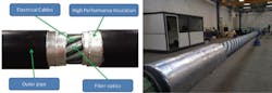
Overview of an electrically heat traced pipe in pipe. (All images courtesy Saipem)
As the heating cables are placed in direct contact with the pipe to be heated below the high performance dry insulation, most of the generated heat is conveyed to the produced fluid. In addition, since the heating cables are operating in a dry and secure environment encapsulated in the pipe-in-pipe annular space, standard field-proven onshore cables and electrical connectors can be employed which have a strong track record of reliable service in other sectors of the oil and gas industry.
To date, subsea EHTPiP systems have been developed for installation via the reeled method. Today, Saipem can offer the technology for J-lay installation, which provides several key advantages:
• No need for a nearby, heavily equipped spoolbase to build and store the pipe-in-pipe stalks. J-lay will be more effective in remote offshore areas with challenging logistics or site conditions.
• As EHTPiP is best suited to long tiebacks, the advantages provided by reeled pipe-in-pipe are diluted by the need for the reel lay vessel to undertake several re-loading trips.
• Reeling also presents limitations in terms of the maximum pipe-in-pipe diameter that can be installed, compared with J-lay, due to the weight and straightening requirement. The typical maximum diameter for reeling is around 18-in., while for J-lay, a 36-in. system can be built.
• Since a J-Lay-installed EHTPiP does not undergo a reeling cycle, the risk of damaging the heating system during the reeling operation is removed.
The main challenge associated with J-Lay installation is to provide safe and reliable electrical connections on every quad joint. It is important to note, however, that electrical connectors have been used for decades in environments much harsher than the annulus of a pipe-in-pipe, which remains a much safer and mire stable environment once installed. To address these challenges, Saipem has placed heavy emphasis on the following key points:
1. A high level of built-in heating system redundancy.
2. Continuous quality control through individual and integrated quad joint electrical and optional fiber optics testing, from onshore manufacturing to offshore installation.
High redundancy
As with most equipment installed subsea, the EHTPiP system must operate throughout its full design life – which often ranges from 20-30 years – without the need for maintenance or recovery. With electrical heating, reliability is all the more critical because failure of this system can jeopardize an entire production line, leading to significant downtime and financial outlay. In addition, if the heating system is designed to be used only during the preservation and/or start-up phases, it is more difficult to detect failures before they become critical, as most of the time the system is inactive.
Typically, offshore operators will insist on 200% redundancy, meaning that where one system is needed, three are provided. This introduces pressures to adopt cost-efficient solutions in order to maintain the economic viability of the overall system. Any improvement that enhances redundancy while not impacting the cost is definitely a key consideration.

FDS2, one of Saipem’s J-lay installation vessels.
Theoretically, the straightforward approach should be to multiply the number of systems in order to increase redundancy. In practice, this is not the case. Adding redundant component implies extra costs, escalating complexity, and issues of congestion brought on by working in a confined space, as is the case for a pipe in pipe system.
With this in mind, Saipem has developed and qualified an end connector that allows for increased redundancy while not requiring any additional components. The connector is designed so that:
• All the cables are electrically connected together on a dedicated ring:
• The ring features lugs that connect the entire system to the inner pipe.
• The fact that the system is operating with three-phase current means that there will be no current at the end junction. All cables will therefore behave in a uniform manner and can be combined without any restrictions, other than the need to activate a number of cables (a multiple of three) in order to maintain the three phases.
This last point results in an improved operational flexibility, and highlights the redundancy generated by each additional cable.
With a conventional EHTPiP system (where cables are only connected in a three-by-three arrangement), the number of installed cables must be a multiple of three, and adding cables on a one-off basis brings no benefit. Take a practical example where the field architecture only requires one set of cables to provide the required heat input. As the system is based on three-phase current, at least three cables are needed for the electrical architecture to function. With a conventional design where the cables are connected in a three by three arrangement, three additional cables must be installed to achieve a 100% redundancy. But adding those cables can be detrimental to the overall insulation performance of the system, leaving less dry insulation space. This can necessitate a wider annular space and a larger outer pipe, hardly an ideal outcome. To achieve the 200% redundancy commonly stipulated, six more cables are necessary instead of three.
With Saipem’s end connector design, however, each additional cable to the original three-cables set immediately provides a 100% additional redundancy - so only two additional cables are required to achieve 200% redundancy. This is due to the fact that if the operator starts the system and detects a fault, the faulty cable can be replaced with any other available cable to restore the initially wanted power in the system. However, with the conventional design a full set of three cables must always be discarded.
Thermal performance then comes into question, as three cables randomly chosen around the pipeline might not generate the same temperature field when compared to a set (with cables at 120° from each other) regularly spaced. The system must be able to generate a temperature field that is homogeneous to guarantee an even temperature of the product.
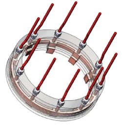
End connector.
In this case, a few considerations need to be taken into account:
• The cables are wound around the pipe with a pitch, which means that their position on the pipe section will rotate along the pipe. Therefore, as the fluid progresses through the line, the heat flux will not be applied on the same radial sector – so from afar, the heat flux will appear as homogeneous.
• Carbon steel exhibits a high thermal conductivity, which will assist even distribution of the heat flux along the entire circumference of the steel pipe.
• Natural convection of the fluid will lead to the temperature being uniform all over the cross-section.
A worst-case scenario is a cross-section where the three active cables are selected to be next to one another. Even in this case, the steel thermal conductivity is sufficient to ensure the heat generated is evenly distributed around the pipe circumference, meaning that any set of three-off cables can generate the desired temperature field. This allows the redundancy level to be raised from the typical 200% to 600%, without an impact in terms of cost and complexity.
Quality control
To ensure comprehensive quality control throughout the pipe fabrication and installation process, Saipem has developed a dedicated test ring. Each quad joint is tested individually onshore, after manufacturing has been completed (i.e. the inner and outer pipes have been assembled into quad joints, the electrical and fiber optic cables installed and insulation applied). This procedure verifies that all components have been properly assembled before sending them offshore and that the obtained readings are accurate. Results can be recorded for quality control.
A second step of testing is performed offshore each time a new quad joint is added to the line being installed. Initially as the fiber optic splice is performed, the connection is tested in order to assess its quality (the attenuation it generates). Then, after all connections have been completed, the full line is tested in order to determine the overall resistance of the electrical cables, ensuring that the connections have been put together as planned, and to measure the attenuation in the complete fiber optic system.
Use of quad joints is another advantage of Saipem’s J-lay installation method compared to long reeled stalks. If a quad joint is found with a defect in the heating system, it can be quarantined: another identical quad joint is immediately available, so operations can be resumed.
The design of the test ring is very similar to that of the connector ring. It features the same capabilities as the connector with additional functions such as power input and data processing output to test the fiber optic and electrical cables along the entire line. The connecting ring performs various resistance measurements on each cable in order to detect a faulty connection. The measurements are then summarized in a graphical interface to indicate clearly to the operator whether the connection is acceptable or not.
Qualification campaign
An extensive qualification campaign has been conducted on the system since 2014. The main aims have been to demonstrate that all components can be integrated together and work as expected; that the achieved performance level is in line with numerical simulations; and to provide testing of specific components when required.
All tests have been performed in Saipem’s workshops or in dedicated laboratories for component testing, i.e. for electrical connectors.
The testing scope in 2014 included:
• Electrical heat tracing system test definition
• Development of design, monitoring system and installation principles
• Preparation and manufacturing of test bench and accessories
• Full-scale manufacturing test
2015 activities were as follows:
• Electrical tests
• Tests of PP and PVDF connectors
• Testing of packers, including characterization of EPDM material
2016:
• Onshore fabrication sequence
• Development and testing of a control ring to check the electrical continuity of all the cables during installation.
Since then, Saipem has offered the system as part of its offshore pipeline capability, and numerous offshore operators have scrutinized the technology in detail, leading to constructive and marginal improvements of the overall system.
References
1. Lirola, F. et al, SAIPEM, Technical assessment and qualification of local and distributed active heating technologies, OMC 2017.
2. Lirola, F. et al, SAIPEM, Innovative and Cost Efficient Heat Traced Flowline with Improved Reliability, OTC-27578-MS OTC Conference Paper – 2017.