Subsea power JIP approaching final test phases
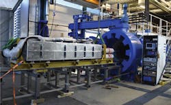
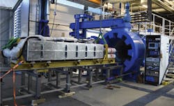
Medium-voltage drive cell pressure test at Statoil’s Rotvoll R&D facility.
(All images courtesy ABB, SPE)
Key step toward all-electric seabed processing
J.Ø. Bugge
S. Ingebrigtsen
ABB
ABB Oil & Gas is managing a joint industry project (JIP) with Statoil, Total, and Chevron to develop technologies for subsea power transmission, distribution, and conversion at greater distances, in deeper waters, and in harsher environments. The project started in 2013 and is targeting a 3,000-hr shallow-water system test in 2018, following the completion of qualification of pressure-tolerant medium-voltage switchgear, medium-voltage drives, and supporting controls and auxiliary supplies.
All three partners and the Research Council of Norway are funding the program, which has a budget of more than $100 million. The main targets are to prove the operability of the equipment in water depths up to 3,000 m (9,842 ft), transmission distances up to 600 km (373 mi), and power levels up to 100 MW.
The project is following a systematic approach of technology qualification for the various components, sub-assemblies and equipment, the aim being to ensure that the technology will function reliably in an offshore field setting within the specified limits, as well as providing improved understanding of risk management. Qualification includes extensive trials of components subjected to test conditions based on a common understanding of component/equipment-specific stresses throughout an agreed life-cycle. Sub-assembly testing is geared mainly to confirming the overall function, design margins, and the thermal and high-current performance.
The new products will provide the power needed for emerging technologies such as subsea compression and subsea oil boosting, and will form part of Statoil’s vision of the subsea factory and the all-electric subsea processing facility. Having power distribution available on the seafloor and the flexibility to take power from shore also enables staged field development without the need for major topsides modifications on remote or deepwater production installations. Ultimately, it could also provide allow production of oil and gas without the need for any topsides installation.
Cost reduction is one of the major drivers behind subsea power. The savings that can be achieved via one long power cable distributed to many subsea loads are substantial. Another advantage of boosting at the seabed close to the wellheads is potentially more optimal recovery of the oil and gas resources; and importing power from shore also leads to lower CO2 (carbon dioxide) compared with power generation on a platform.
VSD prototype
Following verification of the main concept and key components in April 2015, the project passed Technology Readiness level 2 (TRL2). In February 2016, ABB successfully tested a power-switching cell, a critical module of the variable-speed drive (VSD), at 300-bar (4,351-psi) pressure and at full load current at Statoil’s research facility in Trondheim, Norway. ABB has since constructed the first full-scale prototype of the VSD which is due to be shallow-water tested later this year in Vaasa, Finland, over several weeks. The planned 3,000-hr test late next year of a complete subsea power system with two VSDs in a parallel configuration combined with subsea switchgear and controls will also be in shallow water. This will demonstrate full system functionality and interfaces under normal operation and fault conditions to TRL4, the project’s final stage.
The JIP project has allowed flexibility for subsea optimization at all levels. The project organization was defined across several divisions and locations, combining the individual strengths of the system, research and product areas, while at the same time building on long-established experience with subsea transformers.
ABB chose to base the subsea power and control equipment largely on existing in-house technologies with a long record of reliable operation and established quality control and obsolescence strategies. The basic power distribution, conversion, and control principles are equivalent to those for any topsides application. In addition, the company has partly re-packaged other core components for subsea environmental conditions. Subsea-specific features include functions for increased reliability, but with additional margins and redundancies. Since a wide range of electronics and power components need to operate in both a pressure-tolerant environment and dielectric oil, there has been a major focus on component screening and material technologies in relation to chemical compatibilities, material interface aspects, and thermal performance.
All project qualification activities follow the recommendations and TRL stages defined in DNV RP-A203, applicable to components, equipment, and assemblies in hydrocarbon exploration and exploitation offshore. This recommended practice (RP) is designed to ensure that the technology will function reliably within specified limits, and provides a common understanding and terminology of technology status and risk management.
The core process involves a systematic identification of the major challenges and uncertainties to be addressed in the qualification program. This entailed initially a breakdown of the overall subsea power system into separate manageable technology parts, and classifying these in terms of novelty. Other important aspects of the RP are the need to identify required design changes at an early stage and to improve confidence in the new technology through close interactions and traceable documentation.
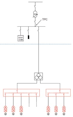
Diagram of a typical subsea power distribution system.
Reliability is ultra-critical for subsea equipment, as it must be designed for long life with minimum intervention for maintenance or repair. The partners agreed on high reliability targets for separately retrievable power and control modules, based on the probabilities of both functioning throughout their first five years in service, and throughout the equipment’s design life. ABB then defined reliability budgets for components and sub-assemblies based on hierarchical breakdowns of the main equipment.
Reliability targets were initially defined as being technically feasible – i.e. relative to existing reliability field data for similar topsides applications – while including risks attributable to the new application area. Initially, targets were also substantiated by a system availability study that involved powering subsea pumps and compressors. However, actual system availabilities for a real subsea deployment will vary depending on the configurations selected.
Subsequent qualification test plans were based on the remaining risk picture, along with an understanding of the actual life-cycle operating conditions and specific operator needs. The team predicted component stresses using mechanical, thermal, and electrical stress simulations, and these served as the basis for accelerated life tests. Critical tests were conducted with immersion in oil under full pressure and at elevated temperature for the duration required to support design life targets, in addition to other component-relevant stress conditions.
ABB has developed subsea-specific laboratories with a range of pressure vessels for component screening studies, as well as for long-term tests on selected components. Test pressures vary depending on the type of investigations, however, acceptance criteria are generally based on tests at 345 bar (5,004 psi) for components in a pressure-compensated environment (non-pressure retaining), and 450 bar (6,526 psi) for pressure-retaining components.
Minimized downtime
The JIP is developing the following main products:
• Subsea medium-voltage (MV) distribution switchgear
• Subsea medium-voltage variable speed drives (VSDs)
• Subsea control and low-voltage distribution.
To ensure compact and reliable solutions, the VSD and the MV distribution are enclosed in oil-filled, pressure-compensated tanks, with components tested extensively under the full pressure they will experience at the target water depth. The aim is to design the equipment such that production downtime and retrievals are minimized.
Power can be supplied from any available topsides installation or from shore. When the step-out distance is long, a higher transmission voltage (e.g. 132 kV) is applied. The step-down transformer converts this to the distribution voltage, typically 11-33 kV. For very long transmission distances, typically 250-600 km (155-373 mi), a low frequency transmission is used (at 16.7 Hz), as normal 50/60 Hz solutions will not be possible.
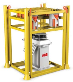
The MV switchgear distributes the main power to the various loads, typically motors for compressors and pumps, and is designed to feed two MV loads. Maximum feeder current is 1,250A, dependent on the availability of subsea connection systems. The switchgear can support an incoming breaker if required as well as a tiebreaker to support cascading of two subsea switchgears. The subsea switchgear has a pressure-compensated design, with two auxiliary supply transformers integrated into the base of the unit.
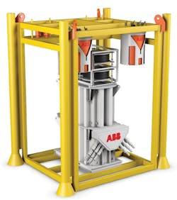
Above: ABB Subsea MV switchgear in a moonpool-installable module. Below: ABB Subsea drive.
A standard dual A/B redundant system provides low voltage supply (auxiliary/control power) to the main power components as well as other auxiliary supply demands: this low voltage supply would typically handle 400V AC (200-600 V) in single- or three-phase mode. The low voltage feeders have integrated isolation transformers and insulation monitoring implemented. A centralized 24 V DC supply system with energy storage maintains control power during transient disturbances on the main supply. Standard oil-filled subsea control modules (SCMs) house the control and low voltage subsea electronic modules (SEMs), filled with nitrogen.
The drive unit is of a pressure-compensated design, with all parts submerged in oil to ensure cooling of the power components. Oil circulating within the drive unit employs natural convection cooling: the unit would typically drive a subsea boosting pump (up to 4 MW), with an output voltage to the motor of around 6-7 kV. Power for the drive comes directly from the subsea switchgear at 11-33 kV. The drive unit includes an integrated drive transformer. For driving larger loads such as compressors, two or three VSD units can be stationed in parallel to drive 12 or 18 MVA loads.
Two VSDs in a parallel configuration will be installed with subsea switchgear and controls, and operated in shallow water for next year’s 3,000-hr trial. The aims are to demonstrate full system function and interfaces under normal operating and fault conditions; to gain reliability experience; and to prove the suitability of the full-scale prototypes including thermal properties, and marinization for a Technology Readiness Level of 4+.
During the test the thermal performance and cooling efficiency of the subsea drives will be closely monitored. It is essential to verify that individual material temperature limits are not violated to achieve the targeted design life. Design-wise and functionality-wise, the units will be as similar as possible to the actual units to be deployed in a future pilot installation; however, the drives will be operated in a back-to-back configuration directly with the grid without motor loads. This is a so-called ‘power-in-the loop’ test where only the power losses needs be supplied from the grid. Testing with a high-power motor load is not performed in seawater, but rather as part of a factory acceptance test.
The final shallow-water sea trial, over 3,000 hours, will involve several stages of testing in seawater in a sheltered harbor. Before running with power, there will be a period of system testing, with various redundant communication tests, black-start sequences, verification of ride-through (energy storage), protection-setting adjustments, breaker and disconnector operations, insulation monitoring system verifications, and operation of the drives with one or more cells out-of-service. During the 3,000-hr test, there will initially be thermal run stability at nominal power. Next, operating point sets and overload conditions will be checked, and then all the drives will run at steady nominal load for a longer period before a final power cycling phase.
Acknowledgment
This is an edited version of the paper Subsea Power JIP – As Enabler for All-Electric Subsea Production, presented at the Offshore Technology Conference in Houston in May 2017, organized by the Society of Petroleum Engineers.
