Under-designed swivel ring flanges potential pipeline problem
With a variety of venders competing in the swivel ring flange market and no industry standard, ensuring product quality has not been easy. However, a failure in the field can be a costly and dangerous event. A swivel ring flange mates to a weld-neck flange. The flange rotates to provide bolt hole alignment. There are no patent involved in the design, so anybody can build one. This is where problems arise.

Except for the weld-neck flange, the swivel ring flange is one of the simplest flanged connectors used in the subsea industry today. There are no industry guidelines specifically suited for their design and manufacture of these flanges. As a result, the swivel ring flange is often designed, manufactured, and sold to offshore operators as little more than a commodity item.
flange is often designed, manufactured, and sold to offshore operators as little more than a commodity item.
A wide disparity in design criteria has developed between the various swivel ring flange manufacturers. Some manufacturers do not fully appreciated the extra-ordinary stresses experienced by this product. Some swivel ring flanges have failed during initial installation. Others failed later, when additional external loads were applied to the pipeline. The failure can be relatively minor, consisting of product leakage past the RTJ gasket. In the worst cases, the flange failed catastrophically, causing a sudden, violent separation of the flange ring from the hub component.
Case histories
A swivel ring flange failure occurred in the Gulf of Mexico about 10 years ago. In this case, a flanged connection on a gas riser was leaking. The divers reported that the gas bubbles appeared to be emanating from the ring gasket area between the flange, a circumstance that would usually indicate the need for additional bolt tightening.
A diver applied increased bolt torque to the leaking flange. Suddenly, the flange failed. The resulting explosion killed the diver. Detailed information on the incident was not readily available, however, it appeared that the initial leakage resulted from a crack in the hub of the swivel ring flange. When the diver applied more bolt load, the crack apparently propagated, causing catastrophic failure. With no additional information, we assumed this was a freak incident, probably resulting from latent materials defect in the hub component.
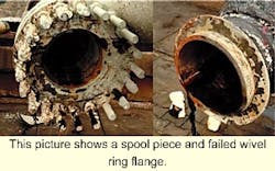
In 1995, Big Inch was mobilized to the South China Sea to repair a damaged oil pipeline. The "damage" appeared to have resulted from the failure and separation of a swivel ring flange in a tie-in spool piece. An examination of this component showed it was a lightweight swivel ring flange - a design that could fail in service.
In this particular case, the line in question was an insulated pipe-in-pipe system designed to handle hot oil. Upon further analysis, it was determined that the line had been subjected to upheaval buckling, which added considerably more load to the spool piece connection. The swivel ring flange proved to be the weak link that failed under this additional loading.
Larger problem
Recent events have shown that the entire industry has under-estimated the scope of the problem. In the past, most offshore operators had large, in-house engineering and purchasing groups that used company technical specifications to purchase products from a pre-approved pool of qualified vendors. However, most operators have since downsized their staffs. More and more of the design responsibility has been outsourced to third party engineering consulting firms and construction companies.
Similarly, an increasing amount of the purchasing function has been outsourced to supply houses. As a result, the offshore operator has been removed two or three steps from the actual purchase of the components that will be placed in their subsea pipeline system.
Outsourcing, in the absence of clear-cut industry standards for ANSI swivel ring flanges, has spurred a proliferation of low cost, lightweight swivel ring flange designs.
In the past few years, Gulf of Mexico operators have experienced several failures of these lightweight swivel ring flanges. Typically, the failures have been minor, causing leakage around the RTJ gasket. In some cases, applying additional bolt load did not stop the leak. Instead, the contractor had to remove the swivel ring flange from the line. Visual examination of these failed swivel ring flanges has shown that the flange ring has been permanently deformed by the bolt load. This "dishing" of the flange ring creates a lift-off force in the area of the RTJ gasket. Applying more bolt load is counter-productive and can potentially caused catastrophic failure.
Recently, Big Inch issued a diver safety alert warning of the potential hazards of tightening these lightweight swivel ring flanges while the line is in service. A simple precaution for the diver is to compare the relative thickness of the rotating flange on the swivel ring flange to that of the mating weld neck flange. If they are identical, the diver can assume he is dealing with a lightweight swivel ring flange.
Applying additional bolt load in such circumstances could create a potentially hazardous situation. When possible, pipeline pressure should be reduced before beginning the bolt tightening process. If additional tightening causes the leak to worsen, no further bolt load should be applied.
Lack of standards
When ordering a standard ANSI weld neck flange, the design guidelines are clear and simple. By specifying a size, class, and a reference to ANSI B16.5 or MSS SP 44, the purchaser has also effectively specified ASTM materials for the body and bolting, methods of manufacture, dimensional information and tolerances, sealing details, and testing and quality requirements. ASME design rules require no further analytical work when the weld neck flange is supplied to ANSI B16.5.
Unfortunately, this is not the case when ordering a swivel ring flange. As indicated earlier, there are no clear-cut industry specifications for swivel ring flanges intended for connection to an ANSI B16.5 weld neck flange. The reason some suppliers have failed to produce a suitably designed swivel ring flange may be that ANSI B16.5 tends to be misleading on the subject of these flanges.
Specifying that a swivel ring flange is made to ANSI B16.5 will give clues as to the quantity and size of bolts and the gasket to be used. It will not guarantee the critical dimensions that determine the strength of the connector.
ANSI B16.5 shows a lap joint flange that might be interpreted to indicate the requirements for a swivel ring flange. The thickness of the hub is specified to be at least as thick as the nominal thickness of the adjacent pipe. ANSI B16.5, however, does not present specific rules for analyzing flanges.
Other design rules, such as those given in ASME, must be used to decide whether the minimum thickness is sufficient for the application. When properly analyzed, it is clear that the minimum hub thickness is only acceptable in the case of small diameter, low pressure flanges.
There are also pitfalls when using ASME for the design of swivel ring flanges. ASME recommends using ANSI B16.5 flanges unless the flange is nonstandard. In the case of a nonstandard flange, ASME Section VIII Division 2 Article AD-720 refers to Appendix 3, "Mandatory Rules for Bolted Flange Connections." Appendix 3 rules are adapted from Taylor Forge and Pipe Works Bulletin 502, Modern Flange Design, in 1938. The rules are given for integral and loose type flanges.
It is the rules for the loose type flange that are misleading. In stepping through the calculations for the flange, the flange moment is determined for the gasket seating and operating conditions. This step is similar to the calculations for integral type flanges. Article 3-340 (b) then instructs the designer to use a set of equations to obtain a stress in the ring portion of the swivel ring flange.
A tangential stress is obtained for comparison to the allowable stresses. Finally, Article 3-350 (e) gives instructions on checking the hub for shear. The problem is that no guidance is given to determine the longitudinal, radial, or tangential stresses in the hub portion of the swivel ring flange. Since ASME does not specifically discuss checking the hub stresses due to the flange moment, one might assume that no further analysis is required.
Clearly, however, both the ring and hub must be analyzed. ASME does attempt to cover this circumstance in Article AD-100 (b). This section states "When complete rules are not provided for a vessel or vessel part ... a complete stress analysis of the vessel of vessel part shall be performed...." One method of compliance is to analyze the hub section of the swivel ring flange as an integral flange. Comparison with the ASME allowable stresses completes the analysis.
Several swivel ring flange manufacturers use the ASME strength criteria as the design basis for a swivel ring flange. These ASME-compliant designs have a proven, track record of durability in thousands of installations. Therefore, when examining the causes of failure in the lightweight, generic swivel ring flanges it is instructive to compare their typical design strength.
Comparison of designs
Not all under-designed swivel ring flanges look alike. Most are easily identifiable by the thickness of the flange ring. For the pressure class of swivel ring flanges used subsea, a flange ring of the same thickness as a standard weld neck flange is insufficient. In addition, there are some cases where a thin hub is obscured by a thick flange ring.
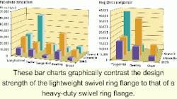
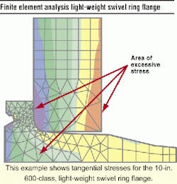
More difficult to detect are the swivel ring flanges that are larger than a standard flange, but insufficient to carry the bolt and gasket loading. Big Inch personnel closely examined several styles of under-designed swivel ring flanges. Using actual dimensional information, the company performed finite element analysis (FEA) on the swivel ring flanges to determine the stresses. Big Inch then compared this data to the strength requirements of ASME Section VIII Division 2 Appendix 3. To illustrate the contrast, the company ran similar strength calculations on its own swivel ring flange design. The results are a comparison of the code requirements with the Big Inch design and the lightweight design. The Big Inch flange ring thickness is 3 3/4-in. thick compared to the lightweight flange thickness of 2 1/2-in. The flange ring thickness of the swivel ring flange is identical to the thickness of a 10-in. 600 ANSI weld neck flange.
Further investigation shows that these non-ASME-compliant swivel ring flanges will use a bored-out weld neck flange or blind flange as the rotating flange ring of the swivel ring flange. The ASME codes stipulate criteria that require a flange ring thickness as much as twice that of a standard weld neck flange. The total weight of the company's own design is 295 lb, compared with 195 lb for the lightweight swivel ring flange. Although heavier does not always equal better, the great variance in the swivel ring flange weights may be an indication of overall fragility of the lighter design.
The lightweight swivel ring flange greatly exceeds ASME stress allowables in both the rotating flange ring and the hub component. The flange ring stresses in the tangential mode are more than double the ASME allowable stresses. Therefore, such a flange fails even the basic ASME calculations. The hub also fails in both the longitudinal and the radial stress mode. The radial stress in this instance exceeds the specified minimum yield strength. In fact, it is close to exceeding the specified minimum tensile strength. It is these areas of weakness that can cause the flange ring to deflect as it is tightened and ultimately cause the ring and hub to catastrophically fail, if additional load is applied.
The example given is not an isolated case. Big Inch has performed similar analyses on several other sizes. Some of these units were removed after they failed to contain pipeline pressure. Others catastrophically failed and separated in service. Samples have included 6-in. 900, 8-in. 900, 12-in. 600, and 20-in. 900 swivel ring flanges. In each case, the swivel ring flange fails in tangential mode in the ring, or the longitudinal and radial mode on the hub. In some cases, as with the 10-in. example above, the failure was in both the ring and hub components. Big Inch also performed a number of checks using FEA of the swivel ring flange. The stress intensity method from ASME Section VIII Division 2 Appendix 4 was used and the values obtained compare reasonably well with the ASME equations.
Proposed remedies
Field experience has shown non-ASME-compliant lightweight swivel ring flange designs can fail in service. The following tips may help avoid inadvertently placing one of these under-designed products in a pipeline:
- Specify that the vendor must confirm full ASME design compliance for the quoted swivel ring flange. Specifying an ANSI pressure class does not guarantee as ASME compliant design.
- Specify that the vendor's proposal must include design calculations to substantiate this ASME compliance of both the ring and the hub.
- Specify that the vendor's proposal must include sketches with critical dimensional data. Some swivel ring flange drawings are not-to-scale. The stock sketch may appear adequate, but may be obviously under designed when viewed as a scaled drawing.
When outsourcing the supply of such swivel ring flanges, include the above requirements in the bid document. Prepare a list of approved vendors for swivel ring flange supply, based on the above criteria. Swivel ring flanges should be handled with the same degree of concern as other critical subsea components.
Until the supply of swivel ring flanges is controlled by codes similar to ANSI B16.5, the responsibility of ensuring that a safe product is installed falls to the operator.
By following these proposed procedures, the operator will be better able to direct the purchasing process toward ASME-compliant designs. In the absence of such guidance, the third party purchaser may make a cost-driven decision, which could well result in the purchase of an inferior, non-ASME-compliant product.
The reduced exposure to potential pipeline failure, environmental damage, and personnel safety is well worth the effort for all parties.