How one of the biggest fields in the US Gulf almost got away

Hull integration, drilling risks highlight Shell's Ursa development
William Furlow
Technology Editor
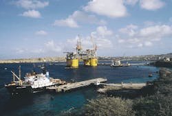
The Ursa TLP found a temporary home in Curacao.While Shell Deepwater Development has as much experience with shallow water flows (SWF) as anyone in the Gulf of Mexico, nothing could have prepared the company for what it faced on the Ursa Field, which underlies Mississippi Canyon blocks 808-810, 852, 853.
Standing in 3,800 ft water depth, Ursa is the deepest application yet of tension leg platform (TLP) technology. Besting Ram Powell, which was installed in 3,214 ft depths nearby, Ursa was a critical step out for TLP technology. According to Shell Construction Manager Bob Jefferis, the additional 600 ft of water made a critical difference in terms of platform design and performance.
The platform moved differently, there were stationkeeping concerns, and the hull itself was much larger than Ram Powell and twice the size of the Mars TLP, which was installed in 2,800 ft of waterin 1996.
Although Ursa was a huge TLP unit, compared to the previous applications of this technology, it would be based on the same design and rely on lessons Shell learned with previous TLPs. Even without shallow geohazards, Ursa would be a world-class challenge. It would require larger topside facilities, to handle production of 150,000 b/d of oil and condensate. The wells would be produced through 5.5-in. tubing, meaning a larger riser system, and tensioners capable of handling 1 million lb each.
The integration of the hull, which was built at Belleli Offshore in Taranto, Italy, and the topsides, would be conducted on site to save time and costs. Typically, integration activities are handled in near-shore shallow water areas. This means lower sea states and less risk.
Integration risk
Shell Construction Process Manager John Haney said everyone told the company not to attempt an offshore integration. But Shell had the experience and confidence in its contractors and managers to undertake the risk. Haney said he was sure Shell could pull it off. The company had been working closely with the same group of contractors on all its TLP jobs, building experience and what he referred to as "value engineering." He explained that Shell and these contractors not only gain experience, but expertise. This, combined with meticulous attention to details made such seemingly risky propositions possible.While there have been a number of high-profile heavy-lift and installation embarrassments offshore this last season, Haney said none was caused by poor engineering. "It is the boring, mundane things that have caused these failures," he said.
Using the skills developed on other TLP jobs, Shell felt it could manage the contractors on Ursa. While other factors intervened to make offshore integration impossible, the close relationship between Shell and its contractors proved invaluable as the project progressed.
Shallow water flow
Ursa comprises four blocks in the Mississippi Canyon (MC) area of the Gulf of Mexico, and is estimated to contain 400 million boe of crude. Development of the field targeted seven potentially commercial sands, which contain 80% of the producible reserves. Shell, the operator, holds a 45% stake in the field; BP Amoco holds 23%; Conoco and Exxon Mobil each hold 16% interest.The Mississippi Canyon area of the Gulf is notorious for shallow water flow (SWF) problems due in part to its proximity to the Mississippi River Delta, only 60 miles away. As Paul Crabtree of Shell explains, the Mississippi River dumps unconsolidated sediments into the Mississippi Canyon area of the Gulf at a rapid rate. These sediments are deposited too quickly to consolidate properly. As more sediment is piled up, water and pressure are trapped below. Eventually, these areas are covered and compressed below thousands of feet of sediment. They remain overpressured and unconsolidated.
When a well taps into one of these sand zones, the overpressured water and sand escape, creating in extreme cases a cavern around the well. Without support for the casing string, the well buckles and collapses. At the very least, these SWF zones cause circulation problems.
Because there is such a delicate balance between the strength of the formation, fracture gradient, and high pore pressure, drilling through these zones is tricky. With such narrow drilling margins, it is difficult to control flow from the formation and avoid damage to the formation.
Discovery wells
From the start of drilling at the site, Ursa would not give up secrets without a fight. According to Shell Drilling Superintendent Bill von Eberstein, even the Ursa discovery well had problems that indicated this would be a difficult field to produce. The discovery well was spudded in 1990 on MC block 854. This well was so damaged by the effects of SWF that the casing buckled across the SWF interval, forcing Shell to abandon it. Generally, the goal on discovery wells and appraisal wells is not only to come away with detailed formation information, but also to drill wells that could later be re-entered and completed. This helps to offset the expense of development drilling.The second discovery well was spudded 141 ft away. While drilling below the 20-in. casing string which was run to 5,000 ft and cemented, a remotely operated vehicle (ROV) detected an increase in flow from the original discovery well when lost returns occurred in the second well. There was no flow at the mudline of the second well. Despite all efforts, returns could not be obtained from the second well.
The well was drilled to the surface casing point at 5,850 ft, and flow from the first well continued. Once the casing was run and cemented, the flow from the first well decreased. The well was continued to total depth (TD) and evaluated. Before drilling a geologic sidetrack, a casing caliper log was run. The log found casing wear in the areas near the SWF zones. During the drilling of the sidetrack, a separate caliper log showed additional casing wear. This indicated the need for a drilling liner, but the casing program did not recommend one. Eventually, the drillpipe stuck in the sidetrack and the well was plugged and abandoned.
Appraisal well
In 1993, the first appraisal well was drilled in MC 809, two miles from the discovery wells. There were plans to conduct extensive evaluations on this well and drill a geologic sidetrack in hopes it would be viable for an extended period. The 20-in. casing string was set at 4,817 ft, 1,022 ft below the mud line (BML). At 5,317 ft, a gain in the returns from the well was detected. The subsea BOP stack was used to close in the well, but there was no pressure buildup detected behind the BOP. The ROV detected flow around the 30-in. structural casing.The well was killed and the 20-in. shoe squeezed with cement to restore the seal between the casing and the formation. This stopped the flow and drilling continued to the 16-in. casing point. The 16-in. casing string was run with partial mud returns and cemented with no returns. The same was true of the next well interval.
On the third well interval, the ROV, which had been monitoring the mudline for returns around the casing, detected seawater flowing from the mudline 50 ft from the well. The ROV also videotaped minor surface cracks in the seafloor, which had not been there before. Clearly, the flow was creating a cavern below the mudline and communicating with the surface.
According to Shell Drilling Engineer Luke Eaton, who presented a paper on Ursa at SPE, there were several possible sources for this flow, because there were several sands in the interval between the 20-in. and 13.375-in. casing shoes. The flow was stopped by perforating the casing and pumping in 5,000 bbl of mud and cement into the formation.
Von Eberstein said Shell takes a "big stick" approach to these flows, putting forward a pre-emptive strike of heavy fluids to kill the flow. While this approach was successful in killing the well, fractures, faults, and "gully-like" features developed in the sea floor. Eaton said these faults were large enough to fly the ROV through.
Drilling then continued to total depth (TD), but a gyro survey of the SWF zones showed buckling of the casing. The flows were eroding away large sections of the formation, removing the support for the cemented casing, and allowing it to buckle under its own weight. While the appraisal well confirmed that Ursa was a viable commercial field, it was clear that drilling would be a challenge.
Preparing for battle
While the first three Ursa wells were less than ideal, Shell learned a great deal from the experience. As the partners prepared to drill production wells, there were a number of innovations they pushed to ensure success. Ursa was ultimately a learning experience, and Shell felt the adventures encountered appraisal drilling had prepared them for what they would face batch processing the production wells.Two areas were focused on by Shell in preparing for these wells. As construction continued on the TLP hull, shell approached vendors with requests for innovative tech nology that could be delivered in a hurry.
- Shell learned from Ursa that more casing strings would be needed. Because the goal was to produce through 5.5-in tubing, Shell would need an innovative casing program offering five different strings instead of three. Eaton said time was such a consideration and the potential of Ursa so great, that this contract was ultimately let on the basis of which contractor could come up with a finished working product in time to keep the project on track.
- The second technology needed was a low-density cement that would set up quickly in the cold temperatures of deepwater. Halliburton came up with a foamed cement that could improve early compressive strength in temperatures of 40° Fahrenheit.
Development drilling
The first site for the Ursa development wells was Mississippi Canyon Block 810. This location was chosen because it was the center of the reservoir. The plan was to use a 24-slot subsea template drilling 14 producing wells. These wells would be located 20 ft apart.At the time the location was chosen, seismic technology was not advanced enough to indicate how deep the SWF zones were in this area of the block or how over pressured they were. Only later, Shell determined one of the SWF sands being drilled was more than 125 ft thick. This thick over-pressured SWF zone combined with the proximity of the wells created what von Eberstein called the most severe shallow water flow conditions ever encountered.
Von Eberstein said there are tricks to drilling through these delicate zones that only experience can teach, but one thing everyone out there understood was that once a well started flowing, it was compromised. Von Eberstein said he could stop the flow, but at Ursa, there was always the question of when and where it would appear again. As with the second appraisal well, the driller might think the problem had been overcome, only to discover a month later that it has worked its way around the cement job and was communicating with the surface.
At the third Ursa well, Shell used its 26-in. riser and subsea diverted system to take returns to the drill floor while drilling the third section of the well - the 26-in. conductor casing. The goal was to set the 20-in. surface casing at 2,000 ft below the mudline (BML). This well was deeper than the previous wells and thought to be safely below the SWF zones.
While drilling the SWF zone, the pore pressure rose and required an increase in mud weight that would equal the fracture gradient at the 26-in. shoe. To avoid fracturing the shoe and losing large volumes of fluid into the formation, the riser was pulled and this section was drilled riserless. A pilot hole was drilled to 5,770 ft pumping seawater.
The hole was under-reamed and killed, using heavy mud. Bottomhole pressure measurements showed that the density of the fluid below the mudline was less than the heavy mud being pumped. A Shell spokesperson said it was theorized the well was losing whole mud to the formation. The well was finally killed using an even heavier mud and drilled to total depth. The cementing of the 20-in. casing was not a complete success.
Logs run to determine the top of the cement revealed that, although the volume of cement pumped should have reached the mudline, the cement stopped 188 ft above the 20-in. shoe. This meant the average diameter of the open hole, from the top of the shoe to the top of the cement, was 50-in. Still tests and logs showed no signs of casing buckling and there were no flows outside the casing, but Shell was concerned that the lack of zonal isolation would lead to future problems.
Pushing out drillpipe
Plans proceeded to batch set the remaining Ursa wells beginning with well number four at a new site. The 36-in. strings and 30-in. strings were set in the corner wells of the template. These wells were drilled to the 30-in. casing point with no flows. When the fifth well was drilled in slot four, 32 ft from the first of the batch set wells, a flow was detected at the 30-in. casing point. Of the remaining 16 strings of 30-in. casing, eight flowed with seawater. Cementing was successful in killing these flows and the 30-in. casing was run on the 20 planned slots. Shell determined that these wells, which were all drilled riserless, were encountering two SWF zones separated by about 200 ft of shale.Pilot holes were drilled in three of the four corner slots to verify the depth of the SWF sands. An inflatable packer was developed to allow for drilling out the shoe, testing the formation and drilling to the 24-in. casing point in one trip. When the fourth and fifth wells in the pattern were drilled out of the shoe, the pressure of the SWF zone was so great, it rocketed 150 ft of drill pipe out of the hole, buckling and damaging the pipe as far up as the mudline. Pressure while drilling indicated fluid flow just below the 30-in. shoe had a density greater than 10.65 ppg, easily defeating the seawater used as a drilling fluid.
Abandoning first site
The massive damage to the batch set wells was discovered when a flow began out of one of the temporary abandoned wells. Open ended drill string was stabbed into the well in an attempt to reach the bottom and set a cement plug in the 24-in. casing. The drillstring hit a bridge at the top of the first sand. A gyro survey run inside the drillpipe showed the pipe had exited the casing at the top of the dogleg. The device also determined there was a 50°/100 ft dogleg in the casing beginning at the sand zone. Gyro surveys were conducted on the other batch set wells and found similar buckling to different degrees. The wells that had been in place the longest had the most severe damage.Stepping back, Shell realized that 10 of the 21 slots at the site were unusable due to buckling. The potential of the remaining slots was weighed against the risk of future problems at the site and time and cost associated with drilling these wells. A decision was quickly made to abandon the site.
In retrospect, Shell said drilling through the SWF zones with returns to the seafloor and pumping seawater in an underbalanced condition aggravated the washouts that led to the problems. Eaton said these washout areas were estimated to be at least 90 ft thick. Although this procedure worked on individual wells, the combined effect of drilling multiple wells this way caused the casing failures.
A second site was chosen about a mile away in Mississippi Canyon block 809. Because the washouts that occurred at the first site originated with the top SWF sand, the new site was selected specifically because seismic data showed the top sand was thinnest at this site. In addition, the decision was made to drill only every other slot in the matrix on the second site in an effort to keep the wells from communicating.
As the first wells were being pre-drilled, the 28,600-ton TLP hull already was under construction. At this point, Ursa quickly became a race against time. The Heerema Balder had been scheduled and contracted for the dramatic offshore integration of the Ursa topsides. The McDermott DB-50 had also been scheduled for the installation of export pipelines at the site. Both these were scheduled before the failure of the initial site.
Now that the new site was being drilled, the timeline had changed. A year and a half of planning and preparation had gone into this integration plan, and suddenly the whole schedule had to be scrapped. At this point, Shell's experience and close relationship with contractors came into play. The delays caused by the change in location pushed the integration back into the hurricane season. This meant the offshore integration plan had to be abandoned. As the Ursa team scrambled to find a near-shore integration site for the topsides, the massive hull began its journey across the Atlantic.
Shift integration
Heerema came up with the idea of using Curacao, an obscure island off the coast of Venezuela, for integration. There were limited port facilities on the island, but it was far enough south to be out of the hurricane zone and had water deep enough to accommodate the Ursa TLP. Curacao is a picturesque Caribbean island, with infrastructure all but nonexistent. The staff and equipment Shell needed for the integration project had to either be flown in or shipped across the Gulf of Mexico on crewboats.Planning for the initial integration project took over 18 months. Planning for this secondary option was completed in only two months and the integration went off without a problem. Every aspect of the project was switched into overdrive. Shell and its contractors raced the clock to make up the six months lost to SWF. Everything that could be done in advance, from crew training on the TLP to site preparation, was done. The 16 tendons were hung off the TLP for more rapid rig-up. When the smoke cleared and the dust settled, the TLP was installed in 30 days, rather than the traditional 90, and the project was back on course to achieve its target first production on March 9, 2000.
Currently, the flair boom is the only remaining piece of equipment that still needs to be installed. Full crews were brought on the rig in the shipyard to accelerate the commissioning and startup of operations.
As drilling continues toward first production, Shell has gained new data about the cause and the severity of SWF zones in the Gulf. Von Eberstein said the 11 wells from which Ursa will be producing will achieve the project's production goals. He is confident, armed with what was learned on the first site, that the project could have included more wells, but the goal was to play it safe and get the project back on track.
"We felt we had to deliver a TLP site. I felt we could solve the problem, but didn't want to push it," he concluded.
Copyright 1999 Oil & Gas Journal. All Rights Reserved.