Barbara Kutchko
National Energy Technology Laboratory, US Department of Energy
The National Energy Technology Laboratory (NETL) and the American Petroleum Institute’s (API) Cement Subcommittee 10C are working together to close the knowledge gap regarding the stability and properties of foamed cement as it is placed in the well. Researchers at NETL are comparing foamed cement samples that were mixed and tested at atmospheric conditions in a laboratory against those generated in the field and collected prior to being pumped into a wellbore.
Strength and stability of cement are critical in protecting the environment from leaks and spills for the life of the well. Foamed cement, created when gases like nitrogen are injected into cement slurry to form microscopic bubbles, is used in formations that are unable to support the annular hydrostatic pressure of conventional cement slurries, such as those commonly found in the Gulf of Mexico. Both the strength and stability of foamed cement depends on the distribution and size of the gas bubbles within the cement. Unstable foams can result in unprotected sections within the well. Stable foamed cement has a consistent density along the length of the column with a homogenous distribution of bubbles throughout the same column, commonly known as bubble size distribution (BSD). It has been shown to have a uniform distribution of spherical, discreet bubbles to ensure that gas will not break out of the slurry.
Foamed cement was developed in the late 1970s in an attempt to eliminate multi-stage cementing. The first foamed cement job on an offshore rig in the Gulf of Mexico was carried out by Glen Benge, a former ExxonMobil engineer, in the early 1990s. Foamed cement soon became the system of choice for the shallow water flows (SWF) that drillers and cementers often found themselves dealing with when operating in the Gulf of Mexico.
Foamed cements have been pumped at depths ranging from several hundred feet to depths in excess of 18,000 ft. In addition to its lightweight density uses, its mechanical properties make it an attractive and efficient solution for a variety of wellbore needs. For example, in comparison to conventional cement, foamed cement is ductile and can deform when the casing is pressurized. As a result, it has a unique resistance to both temperature- and pressure-induced stresses, thus providing resistance to cement-sheath stress cracking. These properties make it ideal for use in hydraulic-fracturing operations, geothermal, and steam-producing wells. Currently, foamed cement is used worldwide for a variety of wellbore environments, both onshore and offshore.
NETL began this research endeavor by mixing foamed cement samples using the current laboratory protocols outlined in the American Petroleum Institute’s Recommended Practice (API RP) 10B-4. This is the same methodology that the industry uses to determine the stability of a foamed cement formula before using it in a well. The API protocols call for mixing the base cement slurry, and then mixing the foamed cement. The base cement is mixed up first in a Waring blender (the same one used in professional kitchens and bars) though the RPM of the blender is controlled.
The laboratory personnel also have a specified amount of time to get the cement into the mix water, again governed by the API protocols. The reason for the attention to mixing the slurry is to get consistent results. It is important to understand that the mixing of a cement slurry in the laboratory by API protocols is not necessarily an attempt to match field conditions, but rather a process to get consistent lab results. Laboratory testing is important to identify problems such as incompatible fluids and for determining the stability of the cement formula. Once the foamed cement is generated, it is tested for stability, strength development and any other tests desired. Just to give you an idea - a well-foamed cement looks and feels like a gritty gray shaving cream.
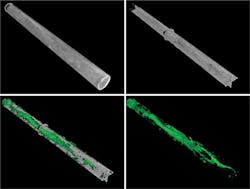
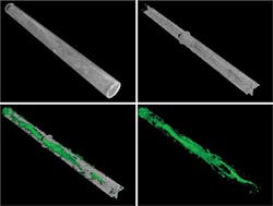
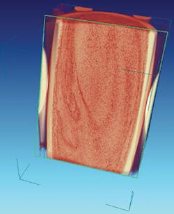
On a rig, foamed cement is generated with temperature and pressure at the surface or well site, and is then pumped into wells through high-pressure treating lines. Therefore, it stands to reason that there will be differences between the laboratory (i.e. blender) and field-generated samples. Working with the API Cement Subcommittee 10C Foamed Cement Work Group, the three major service companies turned to their field testing facilities and successfully collected “field-generated” samples of foamed cement. The foamed cement was collected into pressurized sampling vessels utilizing the same full-scale industrial equipment used to carry out wellbore cementing field operations. These samples were analyzed while still under pressure using NETL’s multi-scale computed tomography (CT) scanning facilities.
NETL and the API’s cement experts quickly observed that foamed cement generated using laboratory (i.e. blender) methods do not look like those generated in the field. The comparison of laboratory and field samples highlight the impact that the cement generating equipment used on a drilling rig has on the properties of the cement. The blender generated foamed cement presented a strong correlation between foam quality (volume of gas in the cement), size of the bubbles, permeability, and strength. Field-generated samples experience many operational variables for use in well construction which can impact the behavior of in-situ foamed cements. It was clear from the CT scans of all three field sample sets that both pressure and flow of the cement slurry through the high-pressure treating lines significantly influence the bubble size distribution. This type of data provides insight into efforts to correlate testing for foamed cement performance in the laboratory that would compare to more representative field behaviors.
As part of NETL’s collaboration with the API Foamed Cement Work Group, all the experimental data is available to the API to help them rewrite the 25-year-old foamed cement testing standard. That data is also available for oil and gas companies to include in their updated models. In addition, API is moving forward with a technical report (TR) focused on foamed cement technology. Unlike other standards published by API, these technical reports allow the publication of material of a technical nature that is not necessarily meant to be a specification or testing protocol. Representatives from each of the individual companies that conducted yard sampling programs have already supplied their summary documentation, and the report will be leaning on NETL for much of the analytical work. The API has only written and published six API TRs in the history of the Cement Subcommittee - thus making this a significant achievement with important impact to the offshore oil and gas industry.
The author
Barbara Kutchko, Ph.D., is senior research scientist at the National Energy Technology Laboratory, US Department of Energy in Pittsburgh, Pennsylvania.
