Bart-Jan Wensveen
Jan-Pieter de Vries
Michael Bell
Ramon de Haas
Heerema Marine Contractors
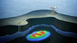
Block 31 NE–PSVM is the first of a string of field developments for BP Angola. PSVM consists of four oil fields: Plutao, Saturno, Venus, and Marte. These fields are geographically dispersed in the northeastern corner of the block. Located in a water depth ranging between 1,800 and 2,100 m (5,904 and 6,888 ft), the development is the deepest in West Africa to date.
All four fields are developed with manifolded subsea production wells producing to the FPSO through pipe-in-pipe production flowlines with a non-insulated service line of the same ID for circulation. The subsea flowline system is connected to the FPSO by means of nine single-line hybrid risers (SLHRs). The SLHRs, installed by HMC'sDCV Balder in 2,030 m (6,658 ft) water depth, are connected to an externally bow-mounted turret moored FPSO. The nine risers cover production, injection, gas lift, and service duties.
The SLHRs consist of a continuous single pipe section supported at the top by a buoyancy tank. The riser connects to the FPSO by a dynamic flexible riser jumper. Gas lift is provided to the base of the production risers via a dedicated gas lift riser and subsea gas lift distribution manifold. Insulation has been added to meet design requirements. The SLHR is connected to the seafloor by a driven foundation pile (including a ballast module).
As the subsea umbilical, riser, and flowline (SURF) contractor, Heerema Marine Contractors (HMC) was responsible for the engineering, procurement, construction, installation, and commissioning of PSVMs flowline and riser scope. The following presents the PSVM deepwater riser construction experience with theDCV Balder, and discusses the intimate link between installation engineering and the detailed design for freestanding risers.

Deepest driven piles
HMC offered a driven pile SLHR foundation as an alternative to the suction pile used in the FEED. The driven pile provided cost benefits to the project and, as driven piles are easier to fabricate, released the desired yard capacity in Angola.
As soil data was only available to 45.5 m (149 ft) penetration depth, the design could not rely on the soil's friction deeper than 45.5 m. Therefore, a separate ballast module was designed and installed to balance maximum riser base tensions.
The connection from the SLHR to the foundation is a flexible joint that is part of the lower riser assembly (LRA). The flexible joint female receptacle was integrated in the driven pile. It was found that fatigue damage from pile driving occurs at the interface between the transition cone and the flexible joint. Based on conservatively chosen hammer energy levels and required number of blows, the factored fatigue damage is 89% of the available life, considering a factor of safety of 10.
Upon the client's agreement to change from suction to driven piles, the spread was prepared in January 2009 at Heerema's Port Fourchon, Louisiana, yard for transportation to Menck in Germany. In Germany, the hammer was overhauled and upgraded to allow pile driving in 2,300 m (7,544 ft) water depth. This was done between May and December 2009.
Before installation, a risk assessment was performed on component level to ensure that the hammer would be fully operational at this record-breaking water depth. The 52-m, 156-metric ton (170-ft, 172-ton) piles were successfully installed at the start of the installation campaign, and are the world's deepest foundation piles, in water depths of 2,030 m.
Buildup of riser string
Different materials and coating combinations were used for the nine SLHRs. The riser installation was scheduled to minimize mode changes in deck and tower work stations. All PSVM offshore welding and onshore preparation was coordinated and carried out by Pipeline Technique Ltd (PTL).
The LRA was brought into the J-lay tower in a dual-crane operation. Thereafter, the riser string was welded to the LRA. Finally, the upper riser assembly (URA) was transferred to the J-lay tower, again in a dual-crane operation. After welding the URA to the riser string, the full riser was lifted out of the J-lay tower and transferred to the riser hang-off structure (RHS) on the other side of the vessel.

Buoyancy tank and connection to SLHR
TheBalder is equipped to handle the buoyancy tanks, which were all built and hydrotested in Angola. The largest tank measured ± 47 m (154 ft) from the top of the main pad-eye to the bottom of the flexible connector, and weighed 240 metric tons (265 tons) in air. Both Balder main cranes were used to upend the buoyancy tanks. Once upended, the buoyancy tank flexible joint was stabbed in the receptacle integrated in the upper riser assembly (URA), and lifted out of the RHS. To improve workability, a dedicated tugger was designed to control buoyancy tank movement during upending and stabbing.
The overall riser installation workability was further improved as tank handling was taken out of the critical path. As mentioned, at theBalder's starboard side the riser string was suspended from a riser hang-off structure, and at this location the buoyancy tank was upended and stabbed in the URA. Concurrent with the subsequent riser string being built in the J-lay tower at portside, changes were performed to allow welding different pipe materials (CRA) and/or allow application of different coating systems as necessary.
Once upended, the top flexible joint was stabbed in the receptacle that was integrated in the URA and lifted out of the riser hang-off structure. At this point the buoyancy tank was ready to be lowered through the water line.

Ballasting and deballasting the tank
Close cooperation with HMC's detailed design subcontractor, 2H Offshore, guaranteed a buoyancy tank design robust enough to cope with various offshore installation (emergency) scenarios. The buoyancy tank was equipped with a piping system used for ballasting (flooding with fresh water or seawater) and deballasting (nitrogen filling) the buoyancy tanks. A frame located externally along the tank accommodates and protects piping, valves, and ROV hot stabs.
The buoyancy tank was ballasted and deballasted via ports on the side of each compartment. This allows for individual control of each compartment. Each compartment features an inlet and an outlet port which are sealed by valves and operated by ROV during riser installation. The deballasting is performed by injecting pressurized nitrogen into the compartment to force out, via the water pipe outlet, any water inside the compartment. After deballasting, the compartments were closed using hot stabs in the outlets.
Hot stabs were required to guarantee a double barrier to prevent seawater entering the buoyancy tank. This meant a saving to the project's valve costs; otherwise, twice the number of valves or double block valves would have been required to provide the double barrier. Qualification testing was done to increase the technical readiness level of the hot stabs. The program included cyclic insertion and extraction of the hot stabs, and low and high pressure testing in hyperbaric chamber.
The water pipe penetrates the outer shell, close to the bottom bulkhead of the compartment. This arrangement ensures the removal of as much seawater as possible. The location of the outlet also gives a slight overpressure after deballasting. Due to this overpressure, should the 4-in. valve not be shut correctly, the nitrogen cannot escape and is trapped inside the compartment.
The piping system design safeguards the compartments from either overpressure or under-pressure. This was achieved by a 3-in. bypass pipe equipped with a valve to ensure that during deballasting, the top compartments are protected from the higher pressure (>2 bar/29 psi differential) required to deballast the lower compartments. Furthermore, the compartments were isolated in groups to ensure that the topmost compartment is not exposed to a pressure greater than the design pressure of 2 bar. This can happen during the deballasting of the lowest compartment in the isolation group if the valve on the topmost compartment in the group leaks.
The buoyancy tank waterline penetration depths and durations were selected to ensure sufficient compartment flooding time. During the procedure, a minimum hook load was maintained to avoid slack slings and to confirm compartment flooding. Flooding compartments were further confirmed by the ROV doing flooding compartment measurements on the tank.
Once the buoyancy tank was below the waterline and filled (including some amount of compressed air), the riser string was lowered to depth with a preset uniform lowering speed, allowing water to flow in to pressure compensate in tank. This was to ensure that a collapse pressure exceeding 2 bar did not occur across the outer shell. With the LRA flexible joint 10 m (33 ft) above the seabed, the buoyancy tank was deballasted until a hookload of ± 80 metric tons (88 tons) was achieved. As the deballasting was done one compartment at a time, there was visual confirmation of the nitrogen bubbles escaping from the 4-in. water pipe on the compartment being deballasted. This effectively ensured that the compartment was fully filled with nitrogen.

Stabbing of riser string
The stabbing operation was performed by theBalder directly stabbing the flexible connector's stem into the receptacle. This does not require a dedicated riser pull down system with winches and catchers, nor does it require an assistance vessel.
The workability assessment indicated that prior to connecting the bottom flexible joint, when the riser is suspended from theBalder's starboard crane, the heave motions of the bottom connector were small enough to allow stabbing of the flexible joint into the receptacle. A safe margin was set on minimum weight to avoid slack rigging during stabbing. During the stabbing procedure, the riser weight was continuously checked by monitoring the deballasting output and the crane hook load.
After connecting the SLHR to the seafloor, the forces in the system increased considerably, and heave compensation was necessary to reduce the rigging forces to acceptable levels. The increased forces were caused mainly by swells in the area that resulted in large crane tip motions. Various options for heave compensation were considered, and the use of stretchers was found to be the easiest and most reliable solution for this installation.
Once the riser was stabbed in the foundation and the riser SLHR was connected with the rigid rigging, the nylon stretcher was tensioned by hoisting the whip hoist and the rigid rigging slacked. Hereafter the buoyancy tank was further deballasted until the rigging could be safely disconnected.
During the project execution, the dynamic models representing different SLHR installation steps were available onboard theBalder. These models, in combination with the weather forecast containing 3D spectral wave data, proved to be excellent for offshore decision making by identifying weather windows.
The predicted system response, based on dynamic models and forecast wave data, was compared with the experience of the offshore crew during installation of the SLHRs. The good resemblance between the predictions and experience contributed significantly to the confidence in the modelling method and predictions. This allowed the offshore crew to fully take advantage of available weather windows.
Both the reliable predictions and the continuous feedback on operational criteria from the installation crew led to a continuous improvement of workability, resulting in maximum vessel availability. The overall weather downtime for the PSVM offshore installation campaign was lower than 3%.
When the stabbing operation was complete, the next riser was being built up in the J-lay tower, or the J-lay tower was prepared for a new welding (corrosion-resistant alloy, or CRA) and/or coating process (injection molded polypropylene, or IMPP).
Determining base tension
When the SLHR was successfully stabbed, the buoyancy tank was aired up to arrive at the pre-determined base tension. This base tension had to be high enough to avoid riser clash and excessive bottom flexible joint angles. The required minimum base tension determined the buoyancy tank size (number of compartments) and the rigid riser pipe wall thickness.
The base tension is a result of the up-thrust of the buoyancy tank minus the submerged weight of the SLHR components. Two independent tension monitoring systems were available during installation.
Although the tension monitoring systems (TMSs) were extensively tested, verified, and calibrated, the tension monitoring systems alone could not give the confidence that the base tensions were met within acceptable tolerances.
Theoretical calculations verified with traveling block load read-outs and onshore weighing of SLHR components were required to supplement TMS readings. This assured that base tensions were within an acceptable range.
Conclusions
With theBalder's successful installation of the PSVM workscope, HMC demonstrated it can execute complex EPCI SURF projects. The complete PSVM installation scope consisted of:
- 51 km (31 mi) of pipe-in-pipe production flowlines
- 40 km (~25 mi) of service flowlines
- 17 km (10.5 mi) of vertical risers
- 77 structures (flowline and riser structures)
- Nine piles driven at 2,030 m water depth
Some major milestones included:
- All installed materials were engineered, procured, constructed, and installed by HMC
- No lost time incidents (LTIs) during the offshore installation campaign
- All work executed against specifications which define new standards for construction and installation of deepwater infrastructure
- Deepest water driven piles ever
- 6,169 offshore pipe welds were produced
- Total weight installed over 50,000 metric tons (55,116 tons)
- Less than 3% weather downtime.
In the closing phases of the project, Heerema ensured that the many lessons learned from this project with regard to detailed design, procurement, fabrication, and installation are retained for future deep-water SURF EPICs.
Acknowledgment
Based on a paper presented at the Deep Offshore Technology International Conference and Exhibition, held Oct. 22-24, 2013, in The Woodlands, Texas.
References
1. PSVM: The Deepest Development in West-Africa, Thanos Moros BP, MCE Deepwater Development, The Hague, March 2013.
2. Monitoring Campaign on Sub-Sea Installation, J. Rodriguez Navarro et al, Heerema Marine Contractors, OMAE Conference, Rio de Janeiro, June 2012
3. Various Detailed Design Reports by 2H Offshore.