Amplitude inversion technique improves subsalt imaging
Laurence Letki
Jun Tang
Charles Inyang
Xiang Du
Robin Fletcher
Jalal Khazanehdari
Schlumberger
The quest for new sources of hydrocarbons has pushed the exploration and production industry into more geologically complex offshore environments that impose greater challenges on accurate geophysical reservoir characterization. While seismic acquisition and imaging techniques have made great technical strides, a disconnect remains between the seismic images obtained and the properties of the rock formation.
Conventional methods of amplitude inversion assume that amplitudes in a seismic image are correctly located and can be inverted to elastic parameters, from which an accurate representation of rock properties can be derived. However, complex geologies—including structurally complex, subsalt, and heterogeneous formations—and limitations in surface seismic acquisition geometries often lead to insufficient illumination of subsurface targets. Conventional amplitude inversion techniques cannot compensate for the resulting amplitude and phase variations of the migrated image. As a result, imprints of various non-geological effects and complex overburdens will carry over into the seismic inversion results, leading to less reliable estimation of acoustic and elastic parameters.
Further complicating amplitude inversion in complex geologic environments is that while depth imaging is normally required to obtain a reliable image of the subsurface, current amplitude inversion techniques are typically implemented in the time domain. This difference in approach between the imaging and inversion steps often compromises the fidelity of the attributes derived from seismic inversion.
As a result, current inversion techniques only provide information on subsurface structure, but no accurate estimates of rock properties such as lithology and porosity. The operator has to make drilling decisions with a high degree of uncertainty regarding prospectivity and volume estimation of the reservoir, and ultimately, the true economic potential of the well.
Depth domain inversion
Schlumberger has recently developed a depth domain inversion technique aimed at improving the consistency between structural imaging and rock property estimation. The technique performs amplitude inversion directly in the depth domain, with a workflow that uses point spread functions (PSF) to capture and correct for space-, depth-, and dip-dependent illumination effects resulting from the acquisition geometry and complex geology. The PSFs represent the spatially and depth-variant 3D wavelet embedded in a migrated image, which replaces the 1D wavelet used in conventional amplitude inversion techniques. The output of this new technique is a reflectivity image and associated acoustic impedance volume corrected for illumination effects, which results in more consistent and reliable imaging products and rock property attributes from depth migrated datasets.
Tackling challenges
Several areas of the Gulf of Mexico present severe imaging challenges related to the presence of thick salt sheets with complex morphology. Modeling studies suggest that adequate subsalt imaging in these areas requires both full-azimuth (FAZ) coverage and long source-receiver offsets. Schlumberger acquired and processed more than 30,000 sq km (11,583 sq mi) of long-offset (up to 14 km, or 8 mi) FAZ data – equivalent to nearly 1,300 outer continental shelf blocks – as part of a multi-client survey program in the Green Canyon area of the deepwater GoM.
The data was acquired using the Schlumberger Dual Coil Shooting mulitvessel full-azimuth acquisition design, in which two recording vessels are deployed with their own sources and with two separate source vessels, all sailing in large interlinked circles. In addition to providing 360° subsurface illumination, this configuration yields a trace density that is roughly 2.5 times that of current wide-azimuth survey designs, which improves signal-to-noise ratio for improved imaging of weak subsalt reflections. It enables the interpretation of subsalt horizons on a reverse time migration (RTM) image.
A part of the dataset from the K2 area of the multi-client survey was studied in further detail. The geological complexity of the salt overburden in this study area led to highly variable levels of illumination, which subsequently negatively impacted the amplitudes and phase of the migrated image. Further analysis of amplitudes extracted along certain horizons showed a correlation with variations in illumination, with areas that are well illuminated with a wide range of offsets and azimuths corresponding to higher amplitudes. Conversely, areas illuminated with a narrower range of offsets and azimuths corresponded to low amplitude areas along the key horizon.
Conventional amplitude inversion techniques are not equipped to compensate for these variations in amplitude or phase. The imprint of non-geological effects such as illumination in the results of seismic inversion severely limited quantitative interpretation. As a result, any attributes derived from amplitudes in the seismic image volume would fail to accurately represent the properties of the corresponding lithology.
Applying the workflow
The new depth domain inversion workflow was applied to the test dataset, with the objective of creating more reliable seismic inversion attributes that were also more consistent with the depth imaging products. The key input to the workflow was a grid of PSFs, which represent the spatially and depth variant 3D wavelet embedded in the migrated image and captures the dip dependent illumination effects due to acquisition geometry and complex geology. In other terms, the migrated image obtained from the FAZ acquisition can be interpreted as the true reflectivity convolved with a blurring operator represented by the PSFs.
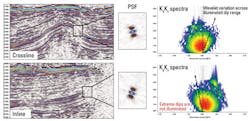
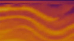
The information captured by the PSFs can be correlated with the amplitude and phase variations observed along the target horizon. The first image presents representative inline and crossline displays through the RTM volume. The PSF corresponding to an area with lower amplitudes has been extracted and analyzed. The KxKz and KyKz spectra of this PSF illustrate strong dip dependence, with the geological dip estimated from the RTM image (shown overlaid on the spectra of the corresponding PSF) lying at the edge of the illuminated dip range. This example observation confirms the effects of variable illumination on the RTM image.
Results
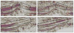
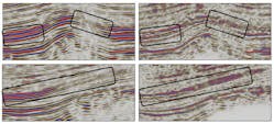
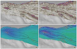
Representative RTM images using source illumination compensation when compared with reflectivity image output from the depth domain inversion shows that the inversion has improved the continuity of major events, delivered an overall sharper image, and revealed details of minor events previously unseen.
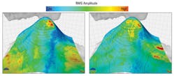
The amplitudes extracted along the key horizon from the reflectivity image also appear more balanced. An amplitude analysis confirms that the amplitudes are less impacted by variable illumination, and more consistent with the subsurface structure. This leads to an increased confidence that these amplitudes can be used to derive more reliable acoustic properties. It should be noted that in areas of very low illumination, the amplitudes on the reflectivity image remain low, as the signal-to-noise ratio is insufficient for adequate illumination compensation. Another limitation of the inversion results appears around high acoustic impedance contrasts, such as the salt boundaries in this case study. The PSF discontinuity across such a high contrast boundary is very high and a simple interpolation of the PSFs is not appropriate. In this situation, a more sophisticated interpolation scheme, a denser PSF grid, or a combination of both is required.
The workflow also produced an acoustic impedance volume corrected for the imprint of the acquisition geometry and complex overburden, enabling an improved structural and quantitative interpretation compared to the time domain inversion.
Conclusions
The depth domain inversion workflow illustrated in this article used point spread functions to capture dip-dependent effects related to acquisition geometry and complex geology. The amplitude inversion was performed in the depth domain and the output was a reflectivity image and acoustic impedance volume corrected for illumination effects. This provided better event continuity, a sharper image, and more reliable amplitude information leading to higher fidelity acoustic impedance results. This enables an improved structural and quantitative interpretation compared to the time domain inversion.
This workflow can also be extended to include more sophisticated physics in the generation of the PSFs, such as incorporating ghost effects or attenuation effects. Including such aspects within the inversion provides a mechanism to produce an even higher fidelity inversion result. •
