Carsten Thoegersen
Emerson Process Management, Valve Automation
High integrity pressure protection systems (HIPPS) are being employed extensively by offshore operators to create the best solution for personnel and asset protection in high-pressure environments. In addition to providing pressure protection, HIPPS are widely considered the most viable solution for required regulatory reductions, including lower flaring and decreased fugitive gas emissions.
Compared with conventional pressure protection systems such as relief valves or rupture disks, HIPPS address many different challenges. One side of the challenge is related to the reliable equipment needed to perform the safe shutdown of the process, while another side is the procedures driving verification, validation, and proof test. These procedures are very important to ensure the required safety integrity level (SIL) is addressed and maintained throughout the entire safety lifecycle of the HIPPS.
Defining HIPPS
HIPPS are part of the safety instrumented system (SIS) and designed to prevent overpressure by shutting off the source and capturing the pressure in the upstream side of the system, thus providing a barrier between the high pressure and low pressure sides of an offshore topsides production facility. The tight shutoff will prevent loss of the containment and eliminate fugitive emissions. In this regard, HIPPS are seen as the "last line of defense."
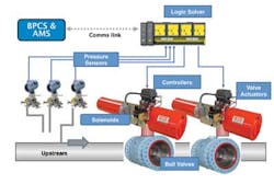
A typical HIPPS will include two or three final elements in series, often required to shut down within 2-3 seconds for gas and 6-8 seconds for liquids, depending on the pipeline pressure, flow rate, and the diameter and class of thepipeline.
The initiator of the shut down sequence (peak pressure surge) will be detected by a pressure sensing system. In the associated diagram, three sensors are connected to the logic solver, which is configured to vote with a 2oo3 logic system (2 out of 3). If the predefined parameters for pressure are exceeded, the logic solver will shut down the final elements and the process.
The 2oo3 configuration is usually preferred for HIPPS, since it provides availability as well as reliability for the system.
Challenges
From an engineering point of view, the challenges faced by HIPPS can be split into three phases: analyzing, designing, and operating (performance) of the HIPPS. These phases are described below.
The analyze phase is critical, and will require the end user/operator to perform a hazard and operating study (HAZOP) and risk assessment to identify potential process risk. Once the risk is identified, a risk reduction factor (RRF) will be selected to ensure that the potential risk is reduced to an acceptable level. The RRF will define the SIL for which the HIPPS will need to be designed (1/RRF = SIL).
Designers are challenged by the lack of standards outlining the design parameters of HIPPS. Whereas conventional pressure relief valves are designed using prescriptive standards like ASME and BS, HIPPS are designed as another safety instrumented function (SIF) tied into the safety instrumented system (SIS). In designing HIPPS, engineering contractors will instead have to use performance-based standards like IEC 61508 and IEC 61511.
In assessing the equipment available on the market today, it is not difficult to source the right components needed to build the HIPPS and verify the system to the required SIL level. The validation is often more critical since the operator will need to ensure that the HIPPS fully meets the requirements outlined in the Safety Requirements Specification (SRS). If discrepancies are found late in the process, the date of "first oil" could potentially be extended.
A well-known analysis of incidents, performed by the UK HSE, reported that 44% of the primary cause of incidents is related to poor specifications. Whereas SIL will protect against random failures, systematic failures due to poor specifications can only be addressed through the use of IEC 61511 in the design phase.
Operating a HIPPS also presents different challenges compared with conventional pressure relief systems. Among end users and operators, there is often seen a fear of losing control during scheduled test. This can result in tests being incomplete or not carried out at all, impacting the required safety level. The safety lifecycle depends on the frequent testing and diagnostic of all components in the shutdown circuit, so rigid procedures or automated tests will be key to safe performance.
Advantages and pitfalls
The design of a HIPPS is often more complex in that the system requires the successful functioning of multiple devices to achieve the same performance as a single pressure relief valve. This means that the calculated reliability of multiple devices: initiator, logic solver and the final element (including valve, actuator and controls) will need to meet or exceed the reliability of a conventional pressure relief valve.
To ensure that the HIPPS system has the correct reliability, engineers need to pay close attention to the basis for the calculated failure rates given by the manufacturer when they select control components. Despite current safety standards that have been known to the industry for more than 10 years, there is a lot of confusion in the marketplace regarding the difference between calculated data (FMEDA), laboratory test results, and field-reported failure data. For example, using data without knowing its origination could be a potential pitfall. A case in point would be taking failure data taken from a high cycle test and using it in the calculation of a HIPPS application, which could have years between full valve strokes.
However, there are clearly more advantages than pitfalls. One of the main advantages is the reduction of fugitive emissions. Although a HIPPS will not be able to fully replace existing systems for pressure relief, it will reduce the number of relief systems required and thereby minimize the need for annual test and its verification. It is a sound and safe way to help operators and end users to reduce fugitive emissions and comply with legislation.
Another clear advantage is that the automated test of the control components of the HIPPS will eliminate the need for personnel onsite to verify pressure relief systems. A fully automated test such as a partial stroke test (PST) can be used to run diagnostics on the critical control components in the shutdown circuit and thereby increase the diagnostic coverage (DC) of the system. For HIPPS with requirements for fast closing < 2-3 seconds, solenoids and pilot-operated boosters can be configured to ensure reliable testing and avoid costly and time consuming spurious trips.
While diagnostics are used to uncover a very high percentage of potential dangerous failures with the system still in service, they could also potentially force the operator to shut down the process if a critical failure is detected. Depending on how critical the HIPPS is for the availability of the plant, a redundant HIPPS can be installed in parallel and used in a "by-pass" configuration during repair.
Addressing all phases
To ensure that all of the challenges in designing, constructing, and operating a HIPPS are addressed correctly, considerable coordination is required among all of the involved parties and component suppliers. Alternatively, an integrated solution with a single source of responsibility is preferred. Not only does that approach address all of the issues faced, but it also provides the operator with a proof test and inspection plan to support the safety lifecycle. It further ensures that the required SIL is maintained throughout the lifetime of the installation.
On the component level, control equipment needs to be supplied with adequate certified failure data to meet SIL3 requirement for HIPPS. These field-proven or verified components include actuators, digital valve controllers, valves, solenoids, logic solvers, and pressure transmitters.
The main advantage to be found with the Emerson solution is the safety consultancy provided, making sure there is a holistic view of the process from front-end engineering over SRS to the validation of the system.


