Frank Lange
Cor Benard
Heerema Marine Contractors
Hervé de Naurois
Total SA
Edward van Duyvenbode
Epsilon Consultancy Ltd.
Dan Lee
Neil Willis
INTECSEA (UK) Ltd.
The need for alternatives to steel catenary and flexible risers has increased with the need for a larger number of risers in deeper water and on congested fields. Together with Total and INTECSEA, Heerema Marine Contractors (HMC) is developing a new riser system that increases the available suite of deepwater riser solutions. It is an offshore constructed hybrid riser bundle installed using heavy lift and pipelay vessels.
The need to evolve the riser concept range is in large part due to the increasing water depth, number of conduits, riser diameters, and the ability of the various types of production floaters to receive the risers. Furthermore, the complexity of the field reservoirs increases insulation requirements for flow assurance, making pipe-in-pipe and heavy wet coating necessary. An important development is the successful introduction of bundled riser towers. These are constructed onshore, then towed and installed on location. A major advantage of these riser towers, apart from the decoupling from the floater motions, is reduced congestion on the seabed compared to the alternative of a large number of single risers. In addition, bundling of risers has economic advantages and mitigates the potential clashing of adjacent risers or structures. A disadvantage is that they are constructed onshore and towed to location. This requires a dedicated bundle fabrication site and, depending on the tow distance, impacts the fatigue of the tower.
The novel concept described herein allows the construction of a bundled riser tower at the installation site, opening up the applicability of bundled riser towers to a larger (and often deeper water) area. Offshore construction can result in a simple and robust in-place design that is easier to inspect, and which offers the opportunity to exchange and remove individual risers or the complete tower.

Although the concept is new, it is based on field proven TLP and pipelay technology. Introducing novel technology to the market requires due consideration of the economic viability, robustness, and safety of the system. This introduction was supported by Total through its evaluation qualification process, in which key risks and areas are identified and mitigated and the system is matured to a project-acceptable level.
The concept is considered sufficiently matured for a West African application and can be developed further to suit an increased payload and/or number of risers for different field applications.
Deepwater riser systems
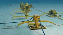
The free standing production riser system tower, often referred to as a free-standing hybrid riser (FSHR) system, can bundle various functions (production, service, umbilical, and export) into a single structure between the seabed and the floating unit.
The FSHR generally is offset from the floating unit using flexibles and has the top of the tower at a depth of around 100 m (328 ft) to reduce the impact of floater motions and wave loads on the tower. This configuration enhances the application in harsh environments.
The development of floating production systems in the 1980s prompted the introduction of free-standing hybrid riser systems. Mobil introduced the first actual free standing application on the Placid Green Canyon field (470 m, or 1,542 ft water depth) in the Gulf of Mexico in 1988. This system was moved to the Ensearch Garden Banks field in 640 m (2,100 ft) water depth in 1994.
In 2001, the onshore-fabricated, towed riser tower, named the hybrid riser tower (HRT), was introduced by Total E&P on the Girassol field in 1,350 m (4,428 ft) water depth. Similar developments followed on Rosa Lirio (Total, 2007) and Greater Plutonio (BP, 2007).
As an alternative to multiple riser towers, the single line offset riser (SLOR) was introduced on ExxonMobil's Kizomba A project in 1,280 m (4,198 ft) water depth (2004).
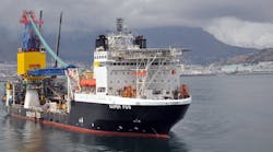
Advantages included the use of offshore construction by pipelay vessels and the ability to install in remote areas where a towed option is not feasible. The SLOR requires more space on the seabed than does an HRT. Similar developments followed on Kizomba B, P52 (Petrobras, 2007), and Cascade Chinook (Petrobras, 2009). The SLOR is also known as single line hybrid riser (SLHR). HMC installed one such system for the block 31 PSVM project where nine SLHRs were installed by the DCVBalder in 2011.
The SLOR concept was further enhanced by the grouped SLOR configuration, a concept that bundles a number of SLORs.
The preferred solution for a specific field requires the assessment of a number of factors related to other components in the development. These include the following:
- Riser system costs
- Track record and operator experience with the concept
- Concept robustness considering inspection and monitoring, maintenance, repair, and replacement
- Field layout and possible congestion
- Floater type (spread moored FPSO, turret FPSO, spar, TLP, or semi)
- Number and type of risers and flow assurance requirements
- Contractor (yard/equipment) availability.
An important advantage of the FSHR is the decoupling of floater and riser motions, and the reduction of payload on the floater. For congested fields, SLOR and bundled riser tower are the preferred solutions, particularly when it involves an increased number of production lines with larger (more than 10-in.) diameters in deeper water.
Novel riser concept
The hybrid exchangeable riser tower (HERT) system is based on offshore assembly of pre-fabricated components using heavy-lift and/or pipelay vessels where the core structure is installed first, similar to the installation of TLP tendons. Thereafter, individual riser assemblies can be installed on the perimeter of the buoyancy tank to create the complete tower.
The HERT is composed of the following main elements:
A foundation structure. Either a driven pile or suction pile arrangement with a roto-latch connection for connecting the tendon. This component is field proven and has been used on previous riser towers.
A tendon string with attached spacer structures. This component is novel but is based on TLP tendon connection technology, allowing offshore construction.
The spacers are intended to avoid riser clashes and to reduce vortex-induced vibration. They are strategically positioned along the length of the riser at varying distances, but at an average of 130 m (426 ft). They allow connection and disconnection of the risers. The tendons are assembled using Merlin Tension Leg Element (TLE) type connectors with the spacers pre-attached to the tendons as in TLP installation.
A buoyancy tank. The buoy requires considerable payload capacity. It carries the weight of the risers, the tendon, including spacers, and part of the flexible weight. The size of the tank can be adjusted accordingly, and the current buoy concepts with diameters in the range of 10 to 13 m (33 to 43 ft) can accommodate payloads from 1,200 to 3,400 metric tons (1,323 to 3,748 tons). The height is governed by the lift height of the cranes given that the tendon string is attached to the buoy at deck level. Although the size and weight of the buoy (on the order of 2,000 metric tons, or 2,205 tons) is considerable, they are well within the capabilities of conventional heavy-lift vessels.
A number of riser assemblies. Consists of a riser segment (single line or pipe-in-pipe) with an upper riser assembly (URA) and a lower riser assembly (LRA). The riser assemblies are hung off at the perimeter of the buoy. Such assemblies are similar to short flowline segments or to SLORs, for which the fabrication and installation are field proven. A URA provides the connection to the buoy (for weight transfer) and a vertical connector for the top spools. An LRA provides the vertical or horizontal connector to the base spool and horizontally fixes the riser to the tower via a base structure with a sliding mechanism to allow for vertical expansion and stroking of the risers.
A top assembly. Rigid spools are used on the top of the buoy between the URA and the flexible jumper. These spools are installed after the flexible jumpers have been installed and fixed on the riser balcony.
A connection system for each flexible jumper. A flexible balcony connects the flexible jumpers to the buoy structure. The flexible jumper is first connected to the buoy and then to the FPSO.
Base spool arrangements. The base spools connect the LRAs with pipeline end terminations (PLETs) on the flowlines. They have configurations similar to previous riser towers and SLORs.
The HERT is installed in the following general sequence:
- 1. Prepare a seabed foundation through a driven pile or the use of a suction pile
- 2. Construct the tendons (with attached spacers) onboard the installation vessel
- 3. Connect the buoy to the tendon string and connect this structure to the foundation
- 4. Build up each riser (including LRA and URA) and lower it on a crane or winch
- 5. Displace the buoy laterally with a tug, and then connect the riser to the tower at the LRA. Continue attaching the all risers to the spacers through combined action of tug and crane, and hang off the riser URA on the buoy assembly
- 6. Lower the base spools and connect the LRAs with the PLETs
- 7. Once the FPSO has arrived, the flexible jumpers can be connected
- 8. Connect the top spools between URA and porches for the flexible jumpers
- 9. Pre-commission the total system.
Key aspects of the novel riser tower technology are:
- Equal functionality compared to "traditional" HRT
- Open tower structure with improved inspectability and, if required, replaceability
- Exchangeability of individual risers or addition of additional risers for phased field developments and/or flow assurance considerations
- Application in remote areas not limited by (bundle wet tow) distance to shore
- Limited fatigue damage to the risers during installation (by avoiding the tow and upending phases)
- All main components can be fabricated locally onshore but the method also allows for competitive bidding from several international yards as the system is assembled offshore
- Installation of the buoy structure can be a separate phase from the riser installation which optimizes schedule options.
Concept design
The concept design of the HERT system for West African application was based on the following:
- 1. Water depth at the FPSO of 1,712 m (5,615 ft)
- 2. Two 12-in./16-in. P-I-P production risers with gas lift through the pipe-in-pipe annulus
- 3. Two 14-in. water injection (WI) risers
- 4. Two 12-in. service line (SL) risers
- 5. Total riser payload (flooded) 2,135 metric tons (2,353 tons)
- 6. High thermal performance
- 7. Remote intervention/maintenance by ROV
- 8. Diverless installation
- 9. 25-year design life.

The system was jointly designed by HMC and INTECSEA using static analysis, response analysis, computational fluid dynamic (CFD) analysis, fatigue analysis of risers and tendon including first and second order, VIV and vortex induced motion (VIM) fatigue, installation and removal design, and design of spacer frame, base structure, URA, LRA, buoyancy tank, top and base spools, and more.
Key aspects were the riser and tendon stress responses and the fatigue performance given the novel application of the spacers. The response analysis under extreme storm conditions showed that the von Mises stress on all the risers and tendon was within the allowable range.
First and second order fatigue analyses were carried out and the results showed that the fatigue damage due to second order vessel motions were minimal. Overall, a minimum factored fatigue life of more than 39 years was achieved for the HERT system, which exceeds the design life target of 25 years.
Fatigue damage assessment of VIV was carried out for the risers and tendon. The results show that the factored life obtained is of the order of 60 years for the risers and 100 years for the tendon, assuming a conservative VIV fatigue factor of 15. It should be noted that VIV suppression devices (e.g. strakes) are only required for the service line and water injection risers in order to meet the design life requirement.
Resulting characteristics of the designed tower are:
- Total sum of risers submerged weight (flooded) 2,200 metric tons (2,425 tons)
- Buoyancy tank weight 1,675 metric tons (1,843 tons)
- Tendon submerged weight (including spacers, etc.) 335 metric tons (369 tons)
- Maximum lift weight tendon string and buoyancy tank 2,400 metric tons (2,646 tons).
Future development
During conceptual design, the HERT was found to offer a number of options for adjustment to other field conditions such as deeper water and a larger number of risers. The size of the buoy is limited at present by the ability to connect the buoy above water, but it is also possible to connect the buoy submerged, allowing for a longer buoy length. An increased payload can then be achieved by fixing additional buoys to the submerged buoy.
Evaluation qualification program
Key challenges in innovating for the offshore industry are the high standards for health, safety, environment, operability, maintainability, and robustness. Total applies an Evaluation Qualification process to help ensure fast introduction of novel technology before a development enters the project front-end engineering and design (FEED) phase. The Technology Evaluation Qualification is a systematic process with the objective of evaluating new technology and its applicability as well as to enhance its development in an efficient and structured way.
The Evaluation Qualification is a staged process that addresses all aspect of the technology's functionality and operability over its full life cycle.
The hybrid exchangeable riser tower evaluation is a structured process:
- Phase A assesses the actual performance of the technology
- Phase B seeks to understand and characterize the level of maturity of the technology's innovative elements or systems
- Phase C assesses the risk inherent in the technology, and estimates and categorizes the severity of risk (called criticity); identifies mitigation actions to reduce overall risk to an acceptable or manageable level; and most importantly establishes its manageability, i.e. a level of difficulty to actually implement these mitigation actions
Following this classical analysis, the aim is then to address uncertainties associated with this new technology and its application to reduce them in a focused way.
References
1) Lessons learned from the evolution and development of multiple-lines hybrid riser towers for Deepwater production applications; V. Alliot and J.-L. Legras, Stolt Offshore SA; OTC 17683, 2005 Houston.
2) The Greater Plutonio Riser Tower; Daniel de la Cruz and Charles Zimmermann, BP, and Pierre Neveux and Frank Louvety, Acergy; OTC 19929, 2009, Houston.
3) The Evolution of Freestanding Risers; Elizabeth Tellier, Ricky Thethi, 2H Offshore Inc.; OMAE2009-79487, Hawaii.
4) Qualification of the Grouped SLOR Riser system; Daniel Karunakaran, Dan Lee and John Mair, Subsea 7; OTC 19899, 2009, Houston.
Offshore Articles Archives
View Oil and Gas Articles on PennEnergy.com