Clamping system offers additional corrosion protection
Chelsea Sherman
Deepwater Corrosion Services, Inc.
Retrofit technology for extending the design life of older offshore pipelines is now being used to provide cathodic protection for new installations. Retrofit methods of combining electromechanical clamps with independent sacrificial anode systems have proved to be cost-effective compared to traditional methods of pipeline protection.
Clamping technology for pipelines and tubular members gives the option of attaching virtually any kind of sacrificial anode system to a subsea asset to achieve a desired anode current output and design life. Clamps have long been used for retrofitting offshore pipelines that have traditional bracelet anodes nearing the end of their design lives, but more operators are looking into using clamping technology with sacrificial anodes on new installations. The reasons are ease of installation, monitoring capabilities, and the ability to provide a longer design life.
According to the Bureau of Ocean Energy Management (BOEM), there are more than 3,000 operating platforms and more than 25,000 mi (40,234 km) of active oil and gas pipeline in the Gulf of Mexico alone. In addition to active pipeline, there are more than 18,000 mi (28,968 km) of out-of-service pipelines, and more than 1,000 mi (1,609 km) of proposed pipeline. BOEM has records of installed pipeline in the Gulf of Mexico dating back to 1947, so the need to protect offshore pipelines is not new. But the technology being developed for protecting these pipelines has made major advances in both reliability and safety.
Retrofit technology
Many pipelines in the Gulf of Mexico and North Sea are nearing the end of their design lives. This poses potentially major issues for operators, as complications and unexpected costs arise with decommissioning, repairing, and/or replacing pipelines. Many operators choose to keep the pipeline in use for an extended number of years. Monitoring cathodic protection performance helps the operator to proactively protect pipelines while meeting mandated industry regulations.
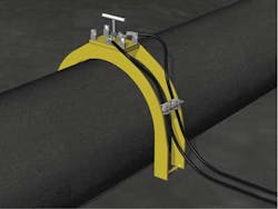
The most cost-effective retrofit solutions involve using single or multiple electromechanical clamping mechanisms along with flexible contact (cabling) to connect a pipeline to an anode array. A sacrificial anode system is beneficial for extremely long and/or deep lengths of pipeline, since no external power or topside cabling is needed. Impressed-current cathodic protection (ICCP), requiring an external power source such as a transformer-rectifier, can also be a beneficial solution in certain situations. Intentionally connecting, or grounding, a shorter pipeline to a structure can also provide adequate cathodic protection to the pipeline in some cases.
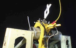
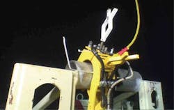
For any type of cathodic protection, the most important component is a secure and reliable means of electromechanical (metal-to-metal) connection between the protected steel entity and the anode array. Current flows in the low-resistance electrically continuous metallic path from the steel to the anode material and back to the steel through the electrolyte (seawater), completing a circuit. If the electromechanical connection is unreliable or becomes disconnected, the circuit is broken and the anode array no longer protects the steel.
Pipelines usually have a coating that provides a challenge for connection and continuity verification with the underlying steel surface. The clamping mechanism is secured in constant tension around the pipe and uses a steel screw with a specific type of tip (depending on the pipe coating) to safely pierce the coat and make safe and reliable contact with the steel. Flexible contact, in the form of heavy cabling, provides electrical continuity between the clamp and the anode array.
Once properly installed, all components of the retrofit system are electrically continuous and the circuit is complete between the protected pipeline, electromechanical clamp, flexible contact, and anode array. It is imperative that clamp designs provide several safety measures for installation to ensure that no damage occurs to the pipe. Depending on the application and depth of installation, the clamps can be installed by diver or ROV. In addition to providing necessary electromechanical connections, clamps can be equipped with monitoring systems to verify cathodic protection performance. Providing a reliable and cost-effective retrofit solution to a pipeline can extend its life by more than 20 years.
Being proactive in retrofitting existing pipelines is crucial to limiting unexpected costs; waiting for a problem to occur and "patching" problem areas with cathodic protection is a common but often ineffective means of corrosion remediation. Attempting to patch or "boost" a spot on a pipeline with cathodic protection has proved inadequate. Contrary to popular belief, this solution is not limited to just the point of attachment or a small area of the pipe. Many pipelines stretch on for miles, which causes attenuation of the protection current at the patched spot so that the effective change in voltage potential of the pipeline is insignificant. The current flowing in the electrolytic path from the anode to the cathode will attenuate along the length of the pipe, and a significant voltage potential shift at only the area of connection will not be achieved.
In order to design a proper anode array for protecting a pipeline, much information is needed about the pipeline and desired amount of life extension. The information and dimensions required include pipe diameter, wall thickness, length of pipeline, coating type, year of original installation, operating temperature of internal product, line burial, and water depth. Environmental information is also needed, including soil and water resistivity and water temperature.
All available information is used to determine the estimated bare surface area of the steel, so that the amount of current demand can be calculated. This is often computed according to industry standards such as ISO-15589-2 and DNV-RP-F103. The anode array must be designed to provide the amount of current required to protect the length of the pipeline. Anode material composition, weight, and geometry all contribute to the output current provided by the anode array. Sacrificial anodes decompose in order to protect the nobler metal (steel pipeline) from suffering corrosion. Offsetting a sacrificial anode array via the flexible cabling allows for improved current distribution attenuation along the pipeline.
Attenuation occurs outward, from the point of connection between the anode and pipe, along the length of continuous pipeline. Many factors contribute to attenuation, including pipeline length, pipe dimensions, existing coatings, existing protection levels, environmental factors, and boundary conditions such as shorted or isolated connections. A shorted connection causes the pipeline to be electrically continuous with another structure, such as a platform; a shorted connection would act as a current drain and cause more severe attenuation.
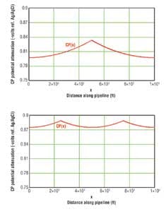
An isolated connection ensures that there is no electrical connection, and thus no current drainage or attenuation between two structures or sections. Both types of connections are useful in certain applications, and it is critical to account for these connections when determining the attenuation of a sacrificial anode system on a pipeline. Attenuation modeling is a main component of a proper retrofit design, and clamping solutions are easy to model and manipulate to determine attenuation and placement of anode systems. Implementing a cathodic protection retrofit solution is an effective preemptive strike for controlling corrosion and ensuring a safe life extension of an entire pipeline.
New pipeline installations
Most new pipelines are installed with a protective coating and several bracelet anodes. Bracelet anodes have been a very popular traditional method of corrosion control in instances of holidays or defects in pipe coatings. However, anode bracelets are not only costly to install over the entire length of the pipeline, but can be easily damaged or cause damage during pipe laying.
Damage can be done to the pipe coating if the anode is dragged, slid, or snagged along the pipe or another entity. Connections can be broken, which would isolate the anode from the cathode and render the anode useless. Due to challenges and costs of installing pipelines with anode bracelets, many operators are moving to retrofit clamping technology to provide cathodic protection to new pipeline installations.
As oil and gas development moves into deeper water, the costs of installation, maintenance, and repair increase rapidly. The benefits of installing a handful of clamp/anode systems versus countless bracelet anodes on a pipeline are obvious. Retrofit technology is subject to thorough quality assurance and testing, can provide a longer design life, can be easily monitored, repaired or replaced, and can be modified to fit many applications and environments. With attenuation modeling and correct placement along the pipeline, a much longer design life can be achieved with these systems than with bracelet anodes.
Clamping technology allows for the connection of completely customizable anode systems to pipelines. The ease of installation reduces the cost and time required to protect the pipe. Clamps with sacrificial anode sleds are currently being implemented on two main production flowlines at a depth of 7,000 ft (2,134 m) in a new GoM field development. Each flowline has a five-layer polypropylene coating that the clamps can easily and safely penetrate, via a steel contact screw, to make contact with the pipe.
Clamping technology may also be applied to other structures, including platforms and subsea equipment, since the clamp design can be made to fit a variety of structural member shapes and sizes. One major operator in the GoM used clamping technology to provide cathodic protection to a cluster of newly installed subsea equipment with a sacrificial anode system with a 45-year design life.
Other recent installations in the North Sea have included the use of clamps with concrete anode mats. This variety of anode solution is suited to areas with high volumetric flow rates and intense environmental conditions, such as the North Sea and Cook Inlet. Monitoring systems can be temporarily or permanently attached to clamps to provide instant confirmation of protection upon installation and verification of system performance during inspections. When considering cathodic protection life-extension alternatives for old or new pipelines, clamping technology can be an extremely versatile solution that offers significant advantages.
References
R. Himiob, "The need for CP retrofit: monitoring and CP life extension of offshore pipelines," Deepwater Corrosion Services, Inc., Houston, TX, 2010.
NOAA. (2012, September 25). The Gulf Region's Contribution to U.S. Energy Production [Online]. Available: http://stateofthecoast.noaa.gov/energy/gulfenergy.html