Mark J. Slaughter
Weatherford
Deepwater pipeline pre-commissioning and in-line inspections are logistical and technical challenges, and vessel time is typically a major expense. The Tamar gas field project in the Mediterranean Sea met these challenges using specialized subsea commissioning technology to mechanically displace and introduce pipeline fluids, and ultrasonic in-line inspection tools to assure pipeline integrity.
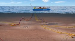
The long-distance, deepwater pipeline project for Noble Energy involved a subsea gas production and transportation system connecting the Tamar gas field to an offshore receiving and processing platform linked to the existing Mari-B platform. The system produces gas from five high-flow-rate subsea wells through separate infield flowlines to a subsea manifold. Dual subsea pipelines transport production from the subsea manifold approximately 149 km (92.5 mi) to the Tamar offshore receiving and processing platform. The processed gas goes to the existing Ashdod Onshore Terminal (AOT) for sales into the Israel Natural Gas Line (INGL).
Weatherford's Pipeline and Specialty Services (P&SS) group was contracted to provide the pipeline pre-commissioning and inspection, including tieback pipelines, monoethylene glycol (MEG) pipelines, infield flowlines, gas and condensate injection pipelines, Tamar sales gas export pipeline, and utility pipelines. Integration of these services through a single contractor was one key to reducing logistical and scheduling constraints for overall project success.
Infield flowline operations
Challenges and solutions engaged in the project revolved around subsea flooding, testing, and MEG injection; dewatering, MEG conditioning, and nitrogen purging; and ultrasonic wall measurement base line inspection.
A key aspect of the pre-commissioning involved flooding, cleaning, gauging, and hydrotesting the 5 x 10-in. deepwater (1,600 m to 1,800 m/5,248 ft to 5,904 ft) infield flowlines of 4-km to 6-km (2.5-mi to 3.7-mi) lengths. These operations were performed from the seabed using Weatherford's Denizen subsea pre-commissioning system.

Flowline operations were independent of the tieback lines and jumper installation. Schedule flexibility increased as a result, and the remote subsea operations avoided the use of a large, vessel-based pumping spread or deepwater downline. Subsea pumps for the flood and hydrotest operations were driven by high ambient hydrostatic pressure during the pipeline free-flood phase and by ROV hydraulic power.
The Denizen pigging pump launched the dewatering pig train with slugs of MEG. A custom, high-volume MEG skid was deployed subsea and connected to the flooding skid to avoid the cost of downline intervention to inject the MEG.
Pre-launching the pigs allowed dewatering of the 10-in. infield lines via a jumper from the 16-in. tieback lines. As a result, all dewatering nitrogen injection was performed from the shallow end of the tieback lines.
Another novel subsea operation used multiple remote subsea data-logging skid packages during hydro-testing. Typically, the ROV and pumping skid hold station at the end of the pipeline for the full 12- or 24-hr pressure test. This was unworkable with five pipelines requiring testing and hold periods.
The solution was to deploy multiple independent hydro-test logging skids. The system's pumping skid has a built-in hydro-test data logging system that displays pipeline pressure, temperature, and pump flow rate. A high-pressure triplex pump, powered by the ROV's hydraulic system, elevated pipeline pressure by injecting chemically treated and filtered seawater.
The logging skids were stabbed into the pipeline and the pressure test was conducted through them. Instead of remaining on station during the hold period, the pump skid was freed to pressurize the next pipeline.
Twin 16-in. pipelines
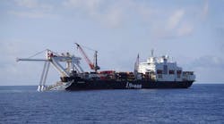
Flooding, cleaning, and gauging the twin 147-km (91.3-mi) x 16-in. pipelines was done from a vessel at the shallow end of the 240-m to 1,700-m (782-ft to 5,576-ft) water depth run. In-line inspection surveys were conducted during flooding. A caliper tool was pumped to verify minimum bore followed by a UTMW tool to acquire the wall thickness baseline survey.
The inspection was followed by dewatering operations for all 5 km (3 mi) of the Tamar infield and tieback pipelines. Pipeline diameter and water depth required a pressure range of 170 to 235 bar (3,465 psi/17 MPa to 3,408 psi/23.5 MPa), which required specialized compression equipment. Weatherford's Temporary Air Compression Station (TACS) fleet provided sufficient compression power to complete the dewatering, MEG conditioning, and nitrogen purging in a single pigging operation.
The procedure eliminated additional post-dewatering pigging/purging, and left the pipelines ready to accept hydrocarbons. MEG batches between pigs in the dewatering train conditioned the post-dewatering residual water and prevented the formation of hydrates. Additional MEG was included for pipe wall desalination.

A novel approach was also used to dewater the 10-in. infield lines via the 16-in. tieback lines without using a downline or a second vessel. The tieback lines were packed to a higher gas pressure (232 bar/3,365 psi/23.2 MPa) than required for dewatering (170 bar). Later, the nitrogen in from these lines was directed through a manifold and set of jumpers to drive the pig trains in the 10-in. infield lines. Because the pig trains were launched earlier, no deepwater downline was required for MEG injection.
Dewatering efficiency was achieved by regulating pig speed using a stab-mounted orifice plate installed at the discharge end of each 10-in. infield line. Days of vessel time were saved by dewatering all five infield lines using the pressurized nitrogen contained in the long tieback lines.
UTWM line inspection
The cost of deepwater repair makes inspection accuracy critical to pipeline integrity assessment. An ultrasonic wall measurement (UTWM) baseline survey was performed on the 16-in. tieback using Weatherford's latest ultrasonic in-line inspection (ILI) tools.
Ultrasound non-destructive testing has been used for in-line inspection since the 1980s. The technology measures wall thickness based on ultrasound compression waves directed into the pipe wall. Ultrasonic transducers positioned 90° to the pipe wall use an impulse-echo mode to transmit an acoustic wave and to receive return echoes. The echoes represent the locations of the internal and external pipe wall, and metallurgical anomalies such as laminations. A UTWM baseline inspection identifies and classifies non-injurious signals such as mid-wall laminations and other mill-related anomalies.
Baseline corrosion survey
Accurate anomaly classification and sizing is valuable when comparing the baseline to future inspection data. Accuracy also enhances future integrity efforts such as engineering assessments and growth rates. It is important for deepwater subsea lines where normal onshore non-destructive examination validation practices are cost prohibitive. A higher level of accuracy is also important when assessing anomalies, assigning risk, and prioritizing maintenance and expenses.

Compared to magnetic flux leakage (MFL) tools, ultrasonic technology results in better sizing accuracy in determining wall loss and pipe wall thickness. This is because ultrasonic pulse echo physics are a more direct measurement of wall loss. In some cases, however, MFL is a better solution because it can be more forgiving of dirt, debris, rough internal pipe surfaces, and waxy liquids. This necessitates a comprehensive pre-inspection assessment prior to selection of the appropriate technology.
Accurate measurement of wall thickness has a direct influence in calculating the failure pressure of a corrosion feature. Typical MFL tools do not measure wall thickness but infer it from API pipe specification, pipeline construction data, and/or estimated variations in the magnetic field. This provides a relative assessment due to pipeline data inaccuracies or difficultly obtaining data because of asset ownership transfers, unavailable data, or unrecorded pipeline reroutes and modifications.
In addition, inferred measurements do not consider wall thickness tolerances from the pipe mill. As a result, an MFL corrosion wall loss depth measurement depends on a relative measurement of the pipe wall. This decreases the sizing accuracy beyond the normal ILI tool sizing tolerance because, in addition to tolerances associated with the ILI tool anomaly sizing, there are also tolerances associated with the actual pipe spool wall thickness from the mill.
Acceptable tolerances from the mill can be as high as ± 10% for pipe wall thicknesses between 5 mm (0.2 in.) and 15 mm (0.6 in.) in welded pipeline. Tolerances for pipe walls greater than or equal to 15 mm are ± 15% in welded pipe. These pipe mill tolerances and the high corrosion-anomaly sizing tolerances of an MFL tool mean the calculated failure pressure from an ILI survey can be significantly over or under as the result of sizing inaccuracies caused by quantifying depths as a percentage of the assumed wall thickness.
More accurate corrosion sizing also provides better data to feed an assessment standard such as B31G, modified B31G, or RSTRENG effective area assessment, the preferred method for determining the remaining strength of the pipe. Of the three, RSTRENG effective area assessment is the most accurate, based on actual versus predicted burst pressure tests.
Experience demonstrates the occurrence of echo loss due to adverse pipeline conditions. New sensor technology in current UTWM devices helps enhance detection and accuracy. API 11636 engineering tests and field data analysis show improved sensitivity and reduced signal degradation, which is critical to a successful deepwater subsea baseline survey. The same sensor technology is used for in-line crack inspection with accurate sizing results that can be used for integrity assessments methodologies such as API 5797.
16-in. tieback inspection
In the Mediterranean operation, tight scheduling for the subsea launch presented a challenge for the 16-in. UTWM ILI inspections. Normally, there would have been sufficient battery life for the inspection tool run. However, in this case a delayed activation was needed because of the time needed for a subsea launch.
The ILI tool first had to be inserted into the pipeline launcher receiver (PLR) onboard the vessel. A vessel crane moved the launcher with the ILI tool to the pipeline end manifold (PLEM). A hydraulic lock secured the pipeline end termination (PLET) to the pipeline, and an ROV was used to turn the subsea valves and launch the pig.
The time-consuming process increased the risk of delays that could drain battery life and cause a failed run. As a result, a two-hour window was included for unforeseen delays. This safety factor led to programing a 12-hour delayed activation from the time the tool was inserted into the PLR onboard the vessel.