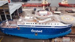
Environment makes special considerations for operations
Phil Fontana
Hans Hansen
Polarcus
There is considerable interest in potential hydrocarbon resources within the Arctic Ocean basin. The basin covers nearly 6% of the earth’s surface and has a shelf area (water depths less than 500 m or 1,640 ft) in excess of 7 million sq km (2.7 million sq mi). Currently there are over 400 oil and gas fields discovered in the arctic region with reserve estimates of approximately 240 Bbbl equivalent, or about 10% of the world’s known reserves. A recent USGS assessment projects the Arctic could hold an additional 412 Bboe of yet undiscovered reserves, with 84% of that volume contained in offshore fields. Five countries: USA, Russia, Denmark, Canada, and Norway - have territory that border the Arctic Ocean basin and can lay claim to the rights to these potential offshore resources.
The incentive to explore and produce these resources has prompted recent offshore exploration activity in the Barents Sea, the Beaufort Sea, the Chukchi Sea, and Baffin Bay, and Davis Straights off the western coast of Greenland. As a first step in any frontier exploration effort, seismic surveys are considered essential to direct the exploration drilling efforts and will also be required in later field development and management stages. However, given the extreme weather conditions coupled with highly sensitive environmental issues, acquiring seismic in the Arctic Ocean basin presents a range of operational and political challenges unlike any other place in the world.
Ship ICE classification
For marine seismic surveys, the first focus is on the capabilities of the survey vessels to navigate and operate safely in arctic sea ice with very low air and water temperatures. International maritime agencies have developed vessel ICE classification systems that specify hull construction, propulsion requirements, winterization systems, and specific maritime operating procedures for vessels in specific arctic conditions at different times of the year. For a vessel to be granted a specific ICE class it must be approved in all these areas, not just one.
For example, a conforming hull design alone does not qualify a vessel for an ICE classification. It must meet the other classification requirements as well.
The following table is an example of ICE classifications defined by the Det Norske Veritas (DNV) one of the world’s leading maritime classification societies.
These designations have been aligned to other national and international maritime classification agency specifications (IACS, FSMA, and RMRS) to provide some coherence in certifying a vessel’s capabilities to operate safely in arctic conditions. The seismic vessel’s ICE classification is important to acquire permits for seismic survey operations in certain areas of the Arctic Ocean during certain times of the year.
The vessel’s ICE capabilities also can impact on how soon a vessel can transit to an operating area and how long it can remain based upon sea ice conditions at the beginning and end of the operating season.
For example, an ICE class 1A vessel may be able to enter an area sooner and stay later than ICE class 1B or 1C vessels. Given the already short operating seasons at these high latitudes, extending the operating time on prospect can have significant implications on an exploration project’s costs and schedules.
Seismic surveys and the environment
As in any exploration area, a seismic survey will be designed to best image the geological objectives in the most accurate and time (i.e. cost) efficient manner. Survey design considerations encompass the required number of survey line kilometers for 2D surveys or the total square kilometers of surface area for 3D surveys. Other considerations are the size of the seismic source signal, the number and length of towed streamers, and the navigation and positioning systems required to provide specified vessel and seismic source and receiver positioning accuracy. On top of the geophysical technical requirements, the technologies used to acquire survey data are required to minimize any environmental disturbance. With that in mind, an examination of the key technologies to manage any possible gaseous, fluid, solid, and acoustic emissions is necessary.
The survey vessel is the possible source for gaseous, fluid, and solid emissions. On most modern seismic vessels, all solid waste material is treated and/or stored onboard until off-loaded by barge or in port. Gaseous emissions are exhaust from the main engines and the engines required for the compressed air supplied to the seismic source. New technologies are being incorporated into modern seismic vessels to reduce SOx and NOx pt in main engine exhaust. COx pt components can be reduced by increasing the overall survey efficiency to reduce the per unit acquisition time for any particular survey area.
Ballast water and fuel oil are the major vessel fluids of concern. Some modern vessels have ballast water treatment systems that can remove contaminates to levels of less than 5 ppm. In addition, there also are systems to neutralize organic matter in the ballast water to prevent introduction of potential alien species into the local ecosystem. However, the primary mitigation for fluid emissions is the integrity of hull of the vessel itself. Double-hull designs offer isolation of any internal fluids from the external skin of the vessel. This is important in arctic regions where a vessel is at risk of a rupture to the outer hull when navigating through ice.
For the seismic systems, the main emissions risk components are the seismic source and the towed streamers. Around the world today, the primary focus on acoustic emissions from a seismic survey is the seismic source. The nature of marine seismic imaging requires the release of a high-level, controlled sound signal into the water. The main question that arises regarding the source is how powerful it needs to be to satisfy the geophysical objectives. For a long time the answer to that question seemed to be that "bigger is better."
However, today, with the degree of scrutiny from government regulators and NGO groups, the recommended approach is to perform a source test at the beginning of a survey to establish the appropriate source level. With the onboard data processing capabilities on most of today’s seismic survey vessels, a test line can be acquired using different levels of source output, the results analyzed on the vessel, and a quick decision made to verify the minimum source level required to meet the survey objectives. A collateral benefit from this is that smaller sources require less compressed air and offer an opportunity to reduce exhaust emission from the air compressors.
Of course, even a "small" seismic source signal generates a relatively loud sound which may disturb a variety of arctic marine fauna. With that in mind, permits for seismic surveys in arctic regions typically require extensive mitigation measures to ensure that any potential disturbances are maintained at the minimum practical level. Mitigation techniques range from visual observations from ships and aircraft to passive acoustic monitoring from the survey vessels and, in some cases, from acoustic monitoring stations deployed on the seafloor. The required sound mitigation adds further operational complexity and downtime risks to arctic seismic surveys which enforce the need for ICE class vessels capable of maximizing the available time on prospect.
The engineering design of towed streamers also offers an opportunity of mitigating fluid emissions. Prior to the mid 1990s, most industrial towed streamer systems were designed around the concept of fluid-filled plastic tubes. Basically, with this design, the seismic signal receiving sensors (hydrophones) are placed in a plastic tube that also contains the towing stress members, power and signal wires, and ancillary devices like depth sensors and communication coils. In order to control streamer buoyancy, the tubes are filled with a low-density fluid to adjust the overall density of the streamer so it can be towed at a specified water depth. For many years the fill-fluid of choice was ISOPAR, a hydrocarbon based fluid known for its low density and electrical insulation properties. Unfortunately, the plastic tubing containing the seismic sensors and the fluid are relatively thin-skinned and are susceptible to pinholes and ruptures from the stress of deployment and retrieval, and also from encounters with objects floating in the water, particularly fishing gear.
In the arctic, thin ice can be a similar hazard. As is obvious, whenever a hole is produced in the plastic tubing, internal fluid leaks into the surrounding water. Given that modern 3D steamer spreads typically have a range of streamers numbering between 6 and 12 with lengths varying between 4,000 m to 8,000 m (13,123 ft to 26,247 ft), it is obvious that a large volume of hydrocarbon based fluid can be towed behind the vessel and that this represents a fluid release risk. Additionally, the seismic survey vessel has to carry a considerable volume of streamer fill-fluid in order to affect repairs and to re-ballast during the course of the survey. Given that these fluids are also highly volatile there is an additional associated fire risk.
In the mid 1990s a new solid streamer technology was introduced into the industry. These streamers use a low-density, solid, plastic material surrounding the tow members, and power and signal wires to control the overall density of the system. With the replacement of low-density fluids by low-density solids, the risk of fluid spills from the steamer essentially is eliminated. An additional advantage of the solid streamer is that it produces an acoustically quieter platform for the seismic signal receivers. The noise performance of the receiver system can impact the level of source signal required to meet a specific geophysical objective – a quieter receiver can accommodate a smaller source level while a noisy receiver will require a higher source level. So, the combination of solid streamers and small seismic sources provides supporting environmental mitigation of both fluid and acoustic emissions.
A complete overview of the seismic acquisition system, including the survey vessel itself, will show that there are many other instances where judicious selection of maritime and seismic technologies can impact both the operational safety and efficiency of a seismic survey in arctic regions while also minimizing the environmental footprint and potential disturbance in the ecosystem. As exploration for and exploitation of arctic hydrocarbon reserves gains pace the seismic industry will be required to further the synergy between maritime and seismic technologies to meet regulatory commitments to maximum safety and efficiency and minimize environmental disturbance.
References
International Association of Classification Societies, Finnish Swedish Maritime Administration, Russian Maritime Register of Shipping.
U.S. Geologic Survey Fact Sheet 2008-3049 (http://pubs.usgs.gov/fs/2008/3049)
DNV
Rules for Classification – Ships
General Regulations, Part 1, Chapter 2, Section 1
Class Notations
