PART I: This is Part I of a two part series on casing drilling, focusing on applications on two wells in the US Gulf of Mexico. Part II, which will appear in February, will deal with more challenging applications.

The 9-5/8-in. surface hole sections of two Gulf of Mexico wells recently were sequentially drilled and cased to depths of 3,222 ft and 3,728 ft, respectively. This was the industry's first offshore casing drilling service with directional steering, and the first casing drilling service for offshore wells provided by Tesco.
The surface hole sections of both wells were drilled through a triple wellhead from a jackup rig cantilevered over the South Timbalier 37 platform. Experience gained in drilling these two wells indicates that the casing drilling process may be used to reduce the time required to drill, case, and cement the surface holes in similar wells by about 20%. The time savings is realized by not having to trip the drillstring.
The two surface hole sections were drilled in a batch process from a three well template within a single 30-in. drive pipe. Both wells were steered directionally to avoid other wells and to position the bottom of the surface casing at a location to facilitate directional work in the next section of the well. The third well was drilled conventionally, building to 47 degrees at 6 degrees/100 ft rate by 2,000 ft course length.
The directional work was done with conventional motors, MWD, and gyro surveying techniques. The well path for the surface hole of both wells included a slight build to 4 degrees inclination while moving away from the platform, and then a dropping back to vertical.
Casing drilling system

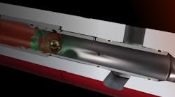
The wells were drilled with Tesco's casing drilling system, where the well is simultaneously drilled and cased by using standard oil field casing as the drillstring. A profile nipple (see accompanying figure) is included near the lower end of the casing to receive a retrievable bottom hole assembly (BHA). The BHA is connected to the casing with a "drill lock" that provides the running/ retrieval interface, the mechanical attachment to the casing, and a hydraulic seal.
The BHA includes a pilot bit and underreamer, as well as all equipment needed for directional steering, such as motor, MWD, non-mag collars, and UR/HO ((underreamer/hole opener).
The pilot bit is normally the standard size that will drift the casing, and the underreamer opens the hole to the standard size normally drilled for the casing. For the 53.50 lb/ft, 9-5/8-in. casing used in these wells, an 8-1/2-in. milled tooth pilot bit was used with a 12-1/4-in. underreamer. Bicenter bits were considered, but could not produce sufficient hole size.
The BHA is designed to be run and retrieved with wireline, but was deployed on drill pipe for this project, due to the weight of the bottomhole assembly (BHA), sticking considerations, and lack of an appropriate wireline unit. This process required that the casing be landed in the hanger so that the blowout preventer (BOP) could be closed around the drill pipe while retrieving the BHA for well control considerations. These procedures were reviewed and approved by the MMS before the well was spudded.
The casing connection used for these wells was a semi-flush integral joint connection providing a trade-off between adequate torsional strength and small upset to minimize interference between couplings on the three casing strings inside the single 30-in. conductor.
At the surface, the casing is connected to the top drive with a "drive sub" which is simply a crossover between the casing connection and 4-1/2-in. IF drill pipe connection. The drive sub includes a drill pipe pup joint to facilitate handling with the top drive and to allow the casing connections to be made with the bit above the top of the pilot hole.
Once the BHA is landed in the casing, drilling proceeds in a manner similar to conventional drilling. The casing is rotated with the top drive for rotary drilling and is slid without rotation for oriented directional work.
Operations description
The 30-in. drive pipe was driven to 357 ft below the rotary table and prepared to receive three separate strings of 9-5/8-in. casing. A centrifugal pump was installed on an outlet 10 ft above sea level to reduce the hydrostatic head of the return mud and to facilitate cuttings removal. The 9-5/8-in. casing for well A-13 was made up with the shoe, shoe joint, and profile nipple, and run and washed down to 353 ft where the casing hanger was landed.

This process was repeated for well A-15. Both strings (A-13 and A-15) were capped and equipped for monitoring the pressure while drilling A-12. These strings were run before initiating casing drilling to assure that all three strings were positioned properly to fit inside the 30-in. drive pipe and to reduce the annular volume and improve cuttings removal.
The rig was skidded over well A-12 and the casing shoe, shoe joint, and profile nipple were made up and run to 339 ft. After running a multi-shot gyro, four joints of casing were laid down to provide room for the directional drilling assembly to extend below the casing shoe.
The drilling assembly, consisting of an 8-1/2-in. milled tooth bit, underreamer, 6-3/4-in. slow speed motor, float sub, 6-3/4-in. MWD (measurement while drilling unit), non-mag UR/HO sub, non-mag drill collar, 8-3/8-in. stabilizer, two 6-1/2-in. pony drill collars, and Tesco Drill Lock, was run on 5-in. drill pipe and landed in the profile nipple. Once landed, the drilling assembly extended about 100 ft below the casing shoe.
Drilling with the assembly proceeded very similar to drilling with a conventional directional assembly. Initial orientations were made with a gyro until magnetic interference diminished sufficiently at 1,100 ft, so that the MWD could be used for orientations. The angle was built to 4 degrees as planned and then dropped back to vertical after sufficient displacement was achieved.
Connections were made by placing a joint of casing in the V-door and installing the Tesco drive sub in the casing and making it up hand tight. The casing joint and drive sub were then picked up with the top drive elevators and made up with the top drive. Drilling in this manner (connection time was 7-10 minutes) continued to a depth of 1,844 ft.
At 1,844 ft, the drilling was interrupted for about 20 minutes and the casing was left in the slips without circulation or pipe movement. Circulation was re-established without any difficulty, but the pipe was stuck, requiring 200,000 lb over-pull to regain pipe movement.
At this point, a decision was made to construct a mouse hole for the 9-5/8-in. casing so that "double" connections could be made to reduce the number of connections needed. While constructing the mouse hole, the mud was converted from a gel-water "spud mud" to a sea water lignosulphonate dispersed system that would normally be used in the next hole section. These two tasks were completed and drilling resumed after 12 hr.
The casing was drilled to casing point at 3,332 ft without further incident. The hole was circulated clean and the casing landed in the wellhead. The BHA was engaged with the Tesco retrieving tool and pulled free with about 5,000 lb over-pull. About 15,000 lb over-pull was observed while pulling the underreamer into the casing, because the arms had not fully retracted. Once the BHA was retrieved, an attempt was made to pull the casing out of the hanger, so that additional joints could be added to lower the casing to bottom. This could not be accomplished due to stuck casing.
A composite cement retainer was run on drill pipe and set at 3,180 ft. The casing was cemented and a temperature log subsequently found the top of the cement at 500 ft. The cement top was planned to be below the 30-in. drive pipe shoe.
The table shows a summary of the times requ-ired for the casing drilling operations in well A-12. The objectives for this well section were accomplished, but there were areas where efficiency could be improved. The directional objective was met, but required more sliding (773 ft) than normal for a similar conventionally drilled well.
Next well
The rig was skidded over A-13 and the casing hanger joint was pulled to the surface and laid down, leaving the casing shoe at 280 ft. A slick BHA assembly with 8-1/2-in. bit was run to a depth of 370 ft to assure the path for the casing drilling assembly was clear.
The casing drilling assembly, identical to the one run in A-12 except that the 1.5 degree bend angle on the motor was changed to 1.83 degrees, was landed in the profile nipple. The bit was washed to bottom with a low flow rate so that the underreamer arms would not extend. A single shot gyro was run and the toolface oriented in the target direction and away from the casing in A-12. A second gyro survey was run to assure that this tool-face had been achieved. In this orientation, the bend in the motor kept the extended underreamer arms from hitting the casing in A-12.
Drilling and surveying proceeded at a somewhat faster pace than with the A-12 well. No difficulty was encountered in nudging the well away from the other platform wells or in steering the well back to vertical. Due to the torsional stiffness of casing compared to drill pipe, there is virtually no offset in tool face direction between surface and downhole or off-bottom and drilling. This speeds up the orientation process by allowing steering from a scribe line on the joint in the rotary, with the MWD being used for confirmation.
The casing was picked up in doubles. Connection time was 6-12 minutes, with 8 minutes being typical. There was no indication of sticking on any of the connections and the torque was quite smooth. Drilling continued with the WOB (weight on bit) being gradually increased to keep the instantaneous ROP (rate of penetration) at about 200 ft/hr until the WOB limit of the underreamer (10,000 lb) was reached. The formation firmed up below 2,000 ft and the ROP fell considerably below 200 ft/hr due to the limited WOB.
Once the casing point (3,838 ft) was reached, the well was circulated clean and the casing was landed in the hanger with the casing shoe at 3,728 ft. The BHA was retrieved without incident; it was latched on the first attempt and pulled into the casing with no indicated weight above the BHA weight.
An accompany table shows a summary of the times required to drill the surface section of well A-13. The overall penetration rate improved over well A-12. The total distance sliding to achieve the directional objectives was reduced from 773 ft to 316 ft. Overall, there was a significant improvement from A-12 to A-13.