The principles of geometry state that "the shortest distance between two points is a straight line." Companies responsible for building pipelines on the continental slopes of our oceans only wish that this law could be applied. Rarely are operators provided the luxury of simply reviewing the sea-bottom from Point A to Point B and then installing a pipeline in a straight line.
The seafloor and near-seafloor geology are typically too complex or constraining to build such a steel lineament. It requires considerably more pre-planning when first deciding where to install a pipeline relative to Point A and Point B. When conducting a pipeline study there are generally four major steps that a design team should consider and implement:
- Review existing regional and site specific data in the area
- Plan a preliminary pipeline corridor
- Conduct a detailed high-resolution geophysical/geotechnical study
- Integrate the geophysics, geology, and geotechnical soils engineering results.
Integrating studies
Mariner Energy Company used a similar approach to the successful design of their Dulcimer Pipeline Project extending from Garden Banks Block 367 to Block 236. Geoscience Earth & Marine Services (GEMS) conducted the preliminary study for this and further completed the interpretations of the final geophysical data collected on the pipeline corridor survey. Intec Engineering was involved in the pipeline design and project management of this study; C&C Technologies conducted the field geophysical operations; Marsco conducted the geotechnical study.
The pipeline route is just west of Geyer Bank, a carbonate hard bank on the upper Louisiana continental slope. Rock outcrop, seafloor faults, expulsion mounds, and other seafloor features extend westward from the Bank. All of these geologic features caused deep concern in selecting a final and feasible route for pipeline deployment.
The direct route approach (Point A to Point B) would have been 64,484 ft in horizontal length. The actual survey showed that the pipeline must be routed around seafloor fault scarps, hard bottom conditions, and seep mounds which increased the horizontal pipeline length to 73,977 ft. The final pipeline corridor had to weave around several constraining geologic conditions The preliminary study greatly reduced the amount of time spent in the field to locate the appropriate route.
Water depths along the pipeline route range from 675 ft to 1,270 ft below sea level with variable gradient ranging from 1% to greater than 40%. Changes in elevation along the route only increased the pipe length by 0.02%, to a total length of 73,993 ft.
Review existing data
There generally is some information available on the regional morphology, seabed character, soils, and man-made infrastructure in an area where production and subsequent pipelines are planned. Too many times, however, this information is overlooked in pipeline route planning.
When pre-planning a pipeline corridor, the planners should consider what work has been previously done in the area, and how much, if any, of this data can be applied to the study. Public information, as well as proprietary data, is generally available in many areas of the world. In the Gulf of Mexico, for example, it is relatively easy to research and find which companies hold the rights on Federal OCS lease blocks, and what man-made infrastructure exists in the general vicinity of the planned pipeline route.
It is equally easy to determine if any high-resolution geophysical surveys have been completed over these lease holdings. Operators can be contacted to request use of such information in the planning of the route. The best interest of the operator may be achieved by working with the pipeline company to plan a feasible corridor for investigation of a route that will fit with the leaseholders plans for development (if any).
In many cases, the original or copied high resolution data is not always available from these surveys. However, the final geohazards reports are relatively easy to obtain either from the operator or from the public information files archived with the US Minerals Management Service (MMS), in the case of the US offshore. The information gleaned from these reports can be compiled into one complete sketch of the seafloor to define the bathymetric and geologic conditions across the corridor.
Other data
Regional data, such as swath bathymetry, and dense data sets such a 3D seismic, can be quite helpful when used properly. When these swaths of data have been collected in over lapping footprints, the resulting data file is a very dense sounding file of the seafloor topography.
Bathymetric maps and profiles can be generated to provide detail of subtle highs and lows along the seabed. The regional bathymetry and profile generation can assist the planners in eliminating terrain that does not look conducive to pipeline installation.
Depending on the density of data, an x,y,z-file of the seabed can then be rendered using one of many imaging software packages to produce a picture of the seafloor terrain. These renderings can provide a very detailed image of the topography, illustrating seafloor irregularities such as: fault scarps, slope instability failures (landslides), hard rock conditions, mounds, vents, chimneys, and other features that would cause concern to pipeline design.
3D seismic
Regional swath bathymetry is not always available over the area to be investigated. The operator may, however, have available 3D seismic data that can be used to pick the seafloor return and produce a similar bathymetry map and seafloor rendering.
Three-dimensional seismic data is generally of very high-quality, and dense coverage (bin-spacing generally 12.5 to 25 meters/bin), so that the seafloor is well represented. In addition, the amplitude of the seafloor can be sampled from these data and a rendering of high-amplitude seabed features can be illustrated.
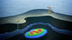
These high-amplitude events generally show areas of hard bottom and/or areas of fluid venting at the seafloor. In the deep waters of the Gulf of Mexico, these vent and hard bottom areas can, be home to chemosynthetic communities.
Survey corridor
When the existing data is adequate, a map can be generated with all known water depth contours, geologic features, and man-made infrastructure. This map can then be used to select a preliminary pipeline corridor to avoid any potential obstructions. Multiple corridors may be selected depending on geologic and man-made obstructions, seafloor slope, pipe length, turns, crossing angle to other pipelines, and other features. Preliminary pipeline corridors may go through many iterations before settling on feasible routes to investigate.
Sometimes, the regional data is not sufficient to select a confident pipeline corridor. This can be especially true in remote areas of the world. One way to overcome this obstacle is to conduct your own area survey. The collection of swath bathymetric data can be done quickly over the area, and can be done with the same survey vessel contracted to perform the pipeline corridor.
Final contour maps, profiles, and renderings can be produced directly on the ship. Qualified geologists and pipeline engineers can select a feasible pipeline corridor directly on the vessel. The corridor can then be surveyed by the same vessel during the same field activity with the high-resolution geophysical suite of equipment.
Field survey
- Geophysics: Once a survey corridor is planned from the review of existing data and/or from the acquisition of swath bathymetry, the next step is to complete the high-resolution geophysical survey. The number of survey lines and line spacing required for the survey depends on the type of lay-barge and/or method of pipe-laying operations. For instance, if a dynamically positioned lay barge is to be used, then an area of approximately 400 meters on a side from the proposed pipeline route is recommended. If an anchored lay-barge is utilized, the survey coverage should extend outward from the barge to the extent of anchorage. The data collected should consist of continuous echo-soundings, or better yet, full swath bathymetry, side-scan sonar imaging of the seafloor, subbottom profiling of the upper 50-100 ft of sediment, and magnetic detection. The benefits of the previous steps is to acquire only the amount of high-resolution geophysical data needed to define the final route.
- Geotechnics: The onboard geologist should map the geologic features during the acquisition of the geophysical data. The geologist and geotechnical engineer should then communicate on the seismic variation in seafloor character to select locations for soil sampling. Piston drop cores and in situ tests collected along the route assist to "ground truth" the geologic interpretations. The collected samples can then be returned to the soils laboratory for further testing.
Traditionally, shallow drop-core samples are taken at intervals along the pipeline route to define the soil properties. Since the pipeline support is essentially influenced by the upper two meters of sediments, it is important that good soil data be acquired throughout this zone.
Pipeline trenching and burial for thermal insulation is another consideration that may need to be studied. Special in-situ tests should also be conducted during the field program in order to provide geotechnical parameters for subsequent design of equipment if trenching and burial is a consideration.
Integrated results
The final step in a pipeline study is to integrate all phases of work into a single, concise geologic model that defines the seafloor and subsurface conditions, and describes that model in a report that is understandable by all members of the pipeline team responsible for the safe installation and use of the pipeline.
The interpreted geophysical/geotechnical data defines an integrated geologic/soil model in three dimensions along the entire pipeline route. Basic interpretative maps can include:
- Bathymetry and seafloor gradient
- Seafloor topography, such as seafloor mounds or fault scarps
- Basic geologic features such as faults, shallow gas, and hydrates
- Soil provinces including variations in geotechnical properties
- Manmade features or debris
- Areas occupied by chemosynthetic communities
- Areas of seafloor instability.
Thus, the final route can be selected with a complete understanding of seafloor conditions (topography, geology, and soils) to avoid regions of irregular seafloor or difficult geologic conditions such as rock outcrops, fault scarps, and other features. Pipeline designers will use the seafloor topography and soil properties along the route to address such design considerations as spanning, settlement, and stability (sliding or erosion of the soils providing the foundation support).
In addition, the topographic data and three-dimensional soil model may be used by the geotechnical engineer to quantitatively assess the slope stability in areas with the steep seafloor gradients. The integrated data will also help select the most favorable site for subsea installations and anchors for a floating production system.
Conclusions
The phased approach to deepwater routing studies provides many technical and financial benefits if performed in a systematic and logical order. The Dulcimer Project illustrates the benefits derived from this approach:
- Existing data is used to the maximum extent to define the complexity of the geologic setting
- Multiple routes can be selected and studied before settling on the more feasible route to be surveyed
- Provides preliminary information to pipeline designers before any survey data has been collected
- Limits the amount of additional geophysical and geotechnical data required
- Decreases geophysical and geotechnical field time, thereby reducing field costs
- Provides a concise geologic/soil model that defines seafloor and subsurface conditions for all pipeline design team members.
The phased approach allows pre-planning with existing data and avoids unnecessary field work, which ultimately saves time and money on deepwater pipeline route surveys.
Acknowledgement
The authors would like to express thanks to Dave Huber with Mariner Energy (Houston), Spinnacker Exploration Company, Pogo Producing Company, Intec Engineering (Houston), C&C Technologies (Lafayette, Louisiana), Marsco (Houston) and Geoscience Earth & Marine Services (Houston).