
Mooring array pre-installed for link-up
George Taylor
J. Ray McDermott

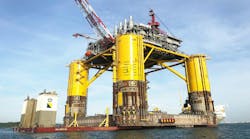
Chevron's Genesis Spar hull is shown before being upended by the DB 50.
- Fabrication of the upper and lower decks for the Genesis Spar. [47,959 bytes]
- The DB50 prepares to lift the lower deck onto the Spar hull, shown upright in the background. [28,991 bytes]
JRM's involvement in the Genesis Spar project included topsides and piling designs; fabrication and procurement; mooring system, hull and topsides installation; facilities hookup and commissioning; and riser design Concurrent engineering/fabrication and installation effort for this fast track project required interaction between Chevron, JRM's fabrication, engineering and installation groups, as well as Mentor Subsea Technology Services. Through teamwork and dedication, the Genesis topsides decks were loaded out within five days of a schedule established two years earlier.
Weights, dimensions
The topsides have a deck surface area of about 100,000 sq ft (3 levels @ 175 ft by 175 ft) and a loadout weight of about 9,000 tons. Nearly 1,200,000 manhours were expended over a 20 month period reaching a 450-man peak in the fabrication yard.The topsides scope consisted of 5,150 tons of structural steel, 2,600 tons equipment installation, and 945 tons interconnect piping, electrical and instrumentation, mechanical completion, commissioning, loadout and tiedown.
The mooring piles had a loadout weight of 3,590 tons. Each mooring pile was 7-8 ft OD by 235 ft long. Each leg of the 14-point mooring system consists of 96-in. diameter anchor pile, 250 ft of 5.25-in. diameter anchor chain, 3,000 ft of 5.25-in. diameter wire rope, and 1,150 ft of hull chain.
The hull is 122 ft in diameter by 705 ft in length. Approximately 178,000 short tons of water ballast were required to upend the hull. The final stage of upending, which brought the hull through over 70° of rotation, took only 76 seconds.
The total weight of the three major installation lifts totaled about 9,000 short tons. A 110-bunk living quarters package and a full API class drilling rig were set onto the top deck level of the spar by J. Ray McDermott's DB 50.
The risers have several features unique to the Spar. These include the keel joint that is designed to withstand the movement of the spar and keep the risers from buckling. The integral buoyancy cans are designed to keep tension in the risers and independently support the riser. To measure this tension, an instrumented joint was installed in the riser string.
Engineering
The engineering design and procurement for this concurrent engineering fabrication project was handled in two phases: front-end engineering (FEE), and detailed design. The FEE scope included preparation of installation plans, electrical lines, equipment arrangement drawings, specifications, and equipment and engineering cost estimates.Detailed engineering was heavily involved with basic topsides design issues. This included the deck's structural design, piping design, electrical design, instrumentation design, topsides equipment specifications, requisition of topsides equipment, inspection and hookup, regulatory issues, preparation of various documents required to commission, start-up and operating the system and field support during fabrication, installation and start-up.
JRM's naval architecture group determined the spar's global motion. Detailed engineering participated in interfacing between topsides and groups performing other services, such as riser design, drilling, and pipelines.
The Genesis topsides were fabricated as two units - production deck and drill/utility deck. Prior to loadout, the drill/utility deck was cut into two pieces (between truss rows 1 and 2) to facilitate loadout.
The topsides scope consisted of the integration of all process equipment, interconnect piping, electrical and instrumentation packages, commissioning, loadout and tiedown.
JRM's scope included the construction of 14 mooring piles, including rolling, stabbing, pad eye installation, loadout and tiedown associated with the mooring piles.
Installation
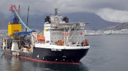
Installation of the Genesis spar was broken into three distinct phases: the mooring system, the hull, and topsides. These phases were performed by JRM's Derrick Barge 50 under a single mobilization.A 14-point mooring system was installed using JRM's deepwater lowering system (DWLS) mounted on the DB50. An anchor pile/hammer assembly with the chain and mooring wire attached, were lowered to the seafloor, positioned, spudded, and driven to final penetration.
After driving a pile, the pre-connected chain and mooring wire were laid out on bottom along pre-determined routes to avoid conflicts with existing pipelines and facilities. The end of each mooring wire was specially outfitted for later retrieval.
Once the mooring system installation was completed, the hull was brought into the field. Upending of the hull was accomplished by a combination of pumping water and staged free flooding. After upending, the hull was positioned near the center of the mooring pattern. A temporary work deck and temporary generators were installed and the 14 mooring lines were attached to the chain jacks on the hull.
After the chains were pulled into the chain jacks mounted on the spar, each chain was locked in place. The entire system was then tensioned to position the spar over location and 10,000 tons of permanent ballast was then installed to increase stability.
With completion of the hull installation, the topsides installation commenced. This included installing a production deck, east and west drilling/utility modules, a quarters package, and a drilling rig.
The installation duration was within one day of the initial estimate established three years earlier.
Risers
The riser team, consisting of Chevron and Mentor Subsea technology services, developed the conceptual designs of three top-tensioned riser systems: production, export, and drilling risers. Sub-systems included:- Drilling riser tensioner system
- Supplemental tensioner
- Export riser bases
- Instrumented riser joints for tension monitoring
- Surface wellhead and christmas trees.
All risers were designed to run with a platform drilling rig, which had to accommodate the large diameter (96 in.) buoyancy cans. Special running tools were designed to handle these large buoyancy cans and the other unique features of the riser strings.
Copyright 1998 Oil & Gas Journal. All Rights Reserved.

![Fabrication of the upper and lower decks for the Genesis Spar. [47,959 bytes]](http://images.pennwellnet.com/ogj/images/off2/1198offgene2.jpg)
![The DB50 prepares to lift the lower deck onto the Spar hull, shown upright in the background. [28,991 bytes]](http://images.pennwellnet.com/ogj/images/off2/1198offgene3.jpg)