Industry shows renewed interest in float-over installation-full
Jonathan Martinez
Dockwise
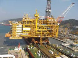
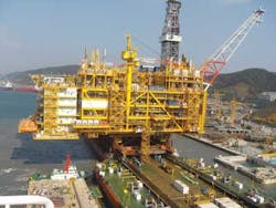
Float-over installation has become an attractive alternative to heavy-lift crane installation for offshore construction, as increasing size and weight of offshore platform topsides continually exceed the lifting capacity of cranes. One out of six units weighs more than 12,000 tons (10,886 metric tons).
Dockwise Ltd. analyzed topsides installation trends from 2005 to 2012, and found that the number of offshore installations has grown over the past decade and is expected to increase in the future. The demand for cost-effective and more flexible alternatives to crane installations was the driving force behind float-over installation using semisubmersible heavy transport vessels (HTVs).
From 2005 to 2012, the offshore crane lift method took the lion's share totaling 115 (44%) of the 264 installations. Yard lift and float-over installations totaled 112 (42%) and 37 (14%), respectively. Of the 264 topsides, 192 (73%) – Type A – weighed between 4,000 and 12,000 tons (3,629 and 10,886 metric tons), and 72 (27%) – Type B – weighed more than 12,000 tons. While 6% of the Type A topsides were installed by float-over, more than one-third of the Type B topsides were installed by float-over. This indicates that float-over installation is growing as a preferred installation method as topsides weight reach 12,000 tons and more.
An estimated 480 Type A and 93 Type B production platforms (fixed, floating, or gravity-based) are expected to be installed between 2014 and 2018. For the majority of Type B units, the offshore installation approach is known: 14 are expected to be installed by float-over, 12 by crane lift, and one by yard lift, 19 are unknown or yet to be decided. A total of 47 FSPOs fall under Type B units, but these units require a different installation approach other than float-over or heavy-lift. Of the 46 Type B productions units within scope (non-FSPO and known installation), 52% of the installation will be conducted by float-over. The majority of the 19 production platforms whose installation approach is unknown or to yet to be decided are expected to be float-over installations.
In the next few years, an estimated 660 offshore platforms are expected to be constructed of which 180 are expected to weigh more than 12,000 tons. The need to develop fields in remote locations where floating and gravity-based production units are required is driving the demand for larger offshore units.
Why float-over?
The float-over installation approach has been proven for more than 30 years, and is regaining interest from the oil and gas industry.
To determine if a float-over installation is the best choice, one needs to review the advantages and disadvantages.
- Advantages
- – Reduced schedule interfaces
- – Reduced risk
- – Capacity
- – Minimize offshore exposure hours
- – Reduced offshore hookup and commissioning
- – Safety
- – Vessel availability
- – Cost savings
- Disadvantages
- – Limited workability
- – Jacket slot requirements
- – Transport and installation support conditions
- – Installation method design implications
- – Early commitment to contractor.
Float-over phases
From an operational point-of-view, there are several distinct phases for a float-over installation starting with the load-out phase. Requirements for the load-out stage are governed by the integrated topsides weight, tidal range, and quayside dimensions. Following load-out, the integrated topsides has to be fastened onboard the vessel for sea transport. After completion of the transit, the vessel needs final preparations prior to the commencement of the actual docking operation of the vessel for the stand-off phase. Preparatory work needs to be executed such as removal of sea fastenings, start-up of mooring/docking/mating winches, start-up of motion and weather monitoring equipment, start-up of active load-transfer system, and pre-ballasting of the vessel.
The vessel is then moved into the jacket for the docking phase. Once the vessel is positioned directly above the jacket structure and docked, the topsides' legs have to be aligned with the jacket legs for pre-mating. Once the topsides is lowered onto the jacket by the vessel's rapid ballasting system where large quantities of water enter the ballast tanks, enabling the vessel to submerge, the mating phase begins. The topsides' weight is completely transferred onto the jacket.
For the post-mating phase, the topsides are secured on top of the jacket and a clearance gap is created between the topsides support unit and the vessel to ensure limited contact between the two. The vessel then departs from the jacket slot on its own propulsion or with assistance from tugs.
Float-over vessel requirements
Three essential criteria are required for an HTV to perform a float-over. The first is the width -- the vessel must be narrow enough to fit inside the jacket slot. The larger-sized topsides (15,000 tons) typically have jacket leg clear spacing of around 151 ft (46 m). Assuming nominal clearances, the vessel width is limited to no more than 138 ft (42 m).
Second, the vessel must be equipped with movable casings and designed with an open stern. To ensure the topsides is perfectly positioned onboard the vessel, the casings, which facilitate balance and ballasting, can be moved to best accommodate cargo. The open stern enables the vessel to exit the jacket slot during the last phase of an installation.
Third, HTVs require sufficient strength and stability to support and transport heavy topsides. Various engineering disciplines ensure the cargo is precisely positioned on board the vessel. Prior to loading, the vessel is outfitted with fixed materials and equipment to safeguard the load-out, transport, and installation. The equipment used depends on the installation requirements.
Mooring system
A mooring system needed for most float-over operations should be sized to accommodate expected vessel motions, site environmental conditions, and site geometry. Mooring lines are made up of either steel or polypropylene lines terminating at steel ropes. The lines and their pretensions are calculated and adjusted to provide precise positioning of the vessel and to minimize the motion. The natural period of the vessel needs to be checked to make sure there are no resonance issues.
The mooring system must be small enough to be deployed and disconnected easily, while strong enough to maintain vessel control. Typically, mooring winches with around 121-ton (10-metric ton) pulling capacity and wire size less than 5-6 cm (2-2.4 in.) in diameter are selected. Anything larger will be difficult to handle offshore or will require special winches. For smaller mating lines that terminate at the jacket legs, 50-ton (45-metric ton) capacity winches work well.
The limitations
Each component of a float-over system will have physical limitations in terms of maximum motions or loads. If these limits are exceeded, safety is compromised, but an iterative process can establish these limitations.
Leg mating unit (LMU) and deck support unit (DSU) component geometry determine the motion limits. Maximum LMU excursion radius is restricted mainly by the substructure leg diameter. The maximum excursion radius rarely exceeds 3 ft (1 m).
Vertical and lateral load limits on the LMU and DSU components are determined by the substructure and the topsides structural strength. Usually, the float-over vessel and the specific analyses are not available at the time of the topsides and substructure structural design, so the limits may be set based on experience.
The mooring and mating lines (and fenders, if used) have limits. Barge motion limitations need to be verified so that the vessel does not contact the substructure. In the final analysis, the wave limits are established as a function of approach direction that will allow safe operations.
Workability
Based on the weather limitations for different directions of weather approach for different times of the year and for historical installation site weather data, the next step is to look at the potential workability for the float-over.
Although the workability thus obtained will not be strictly deterministic, the result will guide the potential weather downtime for a given installation period.
Another decision-making tool that can be installed is the vessel motion monitoring system. In this system, the real-time vessel motion in 3D can be viewed along with its trend. When vessel motions are within limits and the trend is favorable, operations can proceed.

