D. Wiles
J. Davalath
TechnipFMC
Investments in low-cost boosting systems yield high rates of return. Reductions in upfront capex requirements for mudline boosting systems, combined with the increased returns that the systems enable, indicate that mudline boosting can provide the highest return on capital employed (ROCE) amongst competing IOR technologies. Consequently, capital cycle times are reduced, freeing up cash for additional revenue generation.
Analyses of well and reservoir conditions suggest that there are hundreds of wells worldwide that have the economic potential for low-cost subsea boosting systems. The return on investment (ROI) for the subsea boosting system in these cases can range from 250% to greater than 500%.

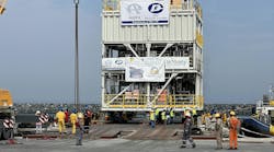
3.2 MW subsea pump module within submerged test pit. (All images courtesy TechnipFMC)
Developments to reduce complexity, introduce standardization, minimize the size and weight of boosting stations, implement integrated project strategies and maximize the use of existing infrastructure in brownfield applications have enabled operators to unlock a tremendous amount of value with subsea boosting systems.
Further, opex reductions, achieved through minimizing startup time with innovative barrier-fluid systems, reducing pump repair and refurbishment time and improving reliability, have reduced the cost of ownership. As a result, multiple subsea boosting projects have been awarded in a low commodity price environment.
To quantify the benefits attainable with the new low-cost boosting systems, a case study was developed which demonstrates the benefit of the addition of a pump to a brownfield installation. The results show that a 500% ROI can be achieved for this case, with oil prices at $50/bbl. Similar results have been obtained in analyses of other fields.
The goal here is to describe the case study that provides guidance on the ROCE benefits, and describe the improvements that have been made to enable such benefits.
Mudline boosting
The need to reduce the backpressure on producing wellheads, and increase the recovery factor from oil and gas reservoirs, is omnipresent in subsea fields. The decision to install subsea boosting at the mudline is made in the context of the incremental improvement in recovery achievable with a subsea pump versus the recovery achievable by producing the field naturally or by other IOR technologies. Operators have studied key oil-producing regions and have identified many instances in which mudline boosting is the most-viable alternative. Additionally, the installation of a mudline pump can enable field-layout optimization and/or increased tieback lengths.
One of the more promising market opportunities for brownfield investment is low-cost subsea boosting systems in deepwater basins. Brownfield applications do not require the drilling of new wells or significant infrastructure investments in new subsea equipment or new topside facilities. Incremental investments in low-cost boosting systems result in substantial increases in revenues and, therefore, high rates of return. Modifications to brownfield systems can be less capital intensive than greenfield developments. As such, they present an attractive investment alternative.
Case study
The economic benefit of the cost reductions can be put into context by reviewing a brownfield subsea multi-phase pump example, the results of which show that by incorporating the innovations described above, the total subsea-boosting-system capex has been reduced by 50%. The potential ROI obtained as a result of the production improvements and capex and opex reductions indicate that between 250 and 500% ROI can be achieved, contingent upon oil prices.
In this example, an existing field is identified to have a low recovery factor and a resultant low topsides utilization, and is hence a candidate for mudline boosting. Other IOR technologies can be analyzed in a similar fashion; the purpose here is to illustrate how the investment in a mudline pump can produce considerable returns. The host facility is located in a water depth of 4,300 ft; fed from wells in 4,000 ft of water. Produced fluids have an API° of 27 and a GOR of 700 scf/stb. Tieback distance is 7 mi. The pump is modeled with the recommended five years mean time between maintenance (MTBM).
High GVFs (gas volume fraction) occur towards the end of the field life when the wellhead pressure is at its lowest. GVF values up to 80% are estimated in 2027. The PM motor is able operate the pump at speeds up to 6,000 rpm and achieve the boost pressure necessary to increase production even during the late life high GVF scenarios, and therefore provide benefits across the life of the field. Consequently, the estimated production improvements show an increase of 31% cumulative oil recovery.
Boosting applications
Subsea boosting systems are a robust and mature technology; worldwide, more than 65 mudline units and more than 50 submersible pumps have been installed. Consequently, 19 operators have addressed production challenges with subsea boosting technology.
Key applications have used subsea pumps as part of a subsea processing station. For example, subsea pumps were installed to boost liquids separated subsea in three-phase separation systems, for the purposes of debottlenecking topside facilities, in the Petrobras Marlim project and the Statoil Tordis project, the former with horizontal pipe separator technology and the latter with conventional horizontal three-phase separator technology.
Subsea pumps have also been installed downstream of gas/liquid separators in Angola’s block 17 in the Pazflor field. This application enabled a higher-pressure boost than could be achieved by multiphase pumps available at that time. The separation of the gas from the liquid enabled the use of a hybrid pump, with centrifugal stages in addition to the helico-axial stages typical of a multi-phase pump, to provide a higher differential pressure. The system also allowed for depressurization as a hydrate management philosophy of, enabling single production flowline architecture, lowering capex and providing a large contribution to the value case for the field development.
Improvements in multi-phase pump technology have occurred such that higher differential pressures can be generated as a result of high-speed motor technology, rapid-control technology, and monitoring systems. Therefore, subsea boosting stations have become less-expensive and more-reliable solutions for increased oil recovery (IOR) are now available.

Technology innovations
To maximize the value created by a subsea multi-phase pump installation, the technology selected must provide an optimal production increase and require low capex and low opex. Furthermore, the installed system must be highly reliable to ensure that revenues can be realized.
The pump-system capex used in the analysis has been by the inclusion of technical and commercial innovations. The term capex for a subsea-pump system, as used in this example, refers to total installed cost, which includes the following:
• Retrievable pump module with mud mat or manifold
• Spare pump module
• Manifold foundation
• Topsides and subsea-pump control
• Topsides and subsea-pump-power infrastructure
• Combined power and controls umbilical
• Subsea-pump-system and umbilical installation.
Developments in capex and opex reductions are described below.
Standardization
Standardization leads to consistent requirements and repeatable quality control processes; such that statistical component reliability data can be established. Costs are saved by the removal of bespoke design engineering activities, which can cascade to require supply chain modifications, production process and procedural changes. Further, standardized components can reduce the cost of product ownership; standardizing increases the reliability of the equipment as it inherently reduces variation in the products and components. The potential for component failure and the cost of component replacement are reduced.
Subsea pump-specific standardization relates to the provision of a set of discrete pump models (frame sizes), each with a power rating selected to meet a market need. Therefore, a wide selection of pumps from low to high shaft power, can be provided and combined with a field specific set of hydraulics to meet the boosting needs.
This is made possible by a fixed hydraulic cartridge length of 12 helico-axial stages, allowing blanks to be inserted if fewer stages are required. Hydraulic cartridge change out during the operating life can ensure that the pump remains optimal if drastically changing field conditions occur. Field specific pressure requirements are addressed using components qualified to discrete pressure ratings relevant to the field, e.g. 5 ksi, 10 ksi and 15 ksi.


Size and weight
A compact pump module design enables a reduction in the amount of pipe and fittings, reducing module weight, which reduces both the pump system cost but also the installation and retrieval costs. A typical design includes minimal permanent subsea infrastructure, with most the pump station equipment contained within the retrievable module. The discipline required to contain all system components within a light-weight retrievable structure has focused the robust system design to include fit for purpose components only.
Existing infrastructure
In brownfield applications, it is possible to utilize existing infrastructure, instead of installing completely new dedicated systems. For example, existing/spare umbilical tubes can be used to transmit barrier fluid and hydraulic control fluid subsea. When no barrier fluid return line is required, this becomes even more feasible. Cost savings and installation and retrieval benefits are therefore introduced. Another example is a tie-in to the existing topsides HPU to remove the need for a dedicated unit. Cost savings and topsides space savings result.
Project execution
Significant cost savings can be realized when technical and organizational interfaces are removed from the project.
A subsea pump project is an ideal example of how the supply of all scopes can be coordinated by a single project manager, such that schedule risk and interface engineering can be minimized. For example, the supply of the power and controls umbilical, the pump station and the installation vessel can be executed by a single capable supplier, with common standards and procedures. Delays in one aspect of the project can be mitigated early, given that all sub-system delivering entities have their interests aligned under one contract. The design can be made to ensure that it is installable by the vessels owned by the supplier. No design is required to satisfy the requirements of a third-party installer. Early engagement between product lines to ensure interfaces are understood and continuous information flow from beginning to end will occur. It is in this way that a true turn-key solution can be delivered at low cost.
Opex reductions
Developments in opex reductions also contribute to maximize the NPV of the investment.
The use of a permanent magnet motor can reduce the power consumed at a given speed, when compared to alternative motor types. The permanent magnet allows for a larger ‘gap’ between the stator and rotor, which results in fewer drag losses.
The need to operate a barrier fluid dehydration unit and/or the storage of hermetically sealed barrier fluid containers, as required for mineral oil based barrier fluids, is removed because of the application of a water-based barrier fluid.
Maintenance costs are reduced; no dehydration unit maintenance, and no high-risk hydrocarbon recirculation system to be maintained. Start-up costs are reduced because water-based barrier fluid circuits do not require circulation require removing moisture from the whole system (umbilical and pump). Therefore, start-up time is minimized.

Subsea boosting technology
The subsea boosting technology utilized in the case study described above is composed of an electrically powered motor coupled to a hydraulic section consisting of impellers to boost the fluid. Power, hydraulic controls fluid and barrier fluid are transmitted subsea via a combined controls and power umbilical, which is terminated at the pump base. The power source is connected to the pump motor via a marinized connection mechanism called a ‘wet mate’ connector. Control fluid and barrier fluid tubes are connected to the pump via hydraulic multiple quick connectors at the pump station. The pump hydraulics selected are based upon the properties of the fluid. In this instance multi-phase hydraulics are utilized, which are composed of helico-axial stages. Multi-phase hydraulics can provide a medium to high pressure boost at GVFs >30%. Single-phase and hybrid hydraulics are also available.
Conclusions
Mudline boosting demonstrates a commercially attractive IOR solution for brownfield tie-ins and long distances tiebacks, in addition to greenfield developments. Capex reductions have been achieved through implementing standardization, reducing size and weight, maximizing the use of existing field infrastructure and integrating project execution.
Opex reductions have been achieved through reliability improvements with the introduction of standardization to reduce variation in products and components, innovative technologies such as the water-based barrier fluid system that addresses challenges to reliability experienced by the industry. Tremendous value has been and will be unlocked by the application of this technology to subsea production scenarios.