Research examines differences between foamed cement slurries in laboratory, field

Barbara Kutchko
National Energy Technology Laboratory,
US Department of Energy
The National Energy Technology Laboratory (NETL) and the American Petroleum Institute’s (API) Cement Subcommittee 10 have been working closely together the past few years to examine the differences between foamed slurries generated with laboratory equipment and field foamed cementing equipment.
When using foamed cement, laboratory testing is employed to estimate the performance characteristics of foamed cement slurries as they are designed for well applications. However, it is well known that significant differences exist between the methods used to generate foamed cement in the laboratory and those used to generate foamed cement for field applications. The implications of these differences on foamed cement characteristics (e.g., bubble size distribution) and performance properties (e.g., stability, permeability, mechanical properties) has not been well analyzed or understood until this research study.
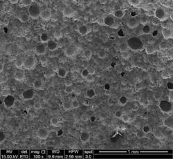
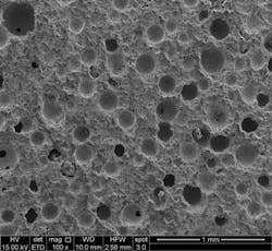
PreviousOffshore articles (September 2014; April 2016) have highlighted the ability of NETL’s CT scanners to thoroughly characterize bubble size distributions (BSD) in both atmospheric and field generated foamed cements. Three independent sampling programs performed by three different major service companies enabled the capture of consistent sets of field-generated foamed cement samples under pressure. Upon analyzing the BSD from the CT data, it turned out that foamed cements generated using the atmospheric blender method [outlined in API RP 10B-4 (2015)] for slurry stability testing in the laboratory, and the current methods used in industrial-scale foamed cementing equipment, do not provide similar BSDs in foamed cements that have similar entrained air/nitrogen volume fractions. Bubbles in the field generated samples were smaller with a different range of sizes when compared to the samples used for testing stability.
So how does this impact the performance of foamed cement in the well?
To answer that, NETL put together a comprehensive plan with a diverse team that involved analysis of field samples, extensive testing in the laboratory, and simulations to address questions that experiments alone cannot answer.
NETL’s geomechanics team has performed robust testing to both the atmospheric laboratory generated and field-generated samples to determine how BSD impacts performance properties. Physical and mechanical properties such as porosity, permeability, Young’s modulus, Poisson’s ratio, bulk modulus, and shear modulus were comprehensively measured. To test the variation in permeability and strength of various foam cements, stepwise pressure loading and unloading experiments were conducted to simulate well pressure cycling. Mechanical properties were obtained under cyclic confining pressures ranging from 12 - 52 Mpa. Thus far, foamed cement samples generated with field equipment display better stability and lower permeability compared to cements generated at the same gas volume fraction as the laboratory samples used to test slurry designs. The resulting mechanical properties of both field-generated and atmospherically-generated foamed cements suggests that a maximum 30 to 35% nitrogen volume fraction is suitable for applications to isolate subsurface formations in oil and gas well cementing operations.
Work is continuing to improve the correlation between current API RP 10B-4 (2015) test methods and foamed cements generated with field cementing equipment. The DOE-NETL has a plethora of data about the BSD from CT scans of the different samples that have been obtained from the field tests and those produced in the laboratory. Simulations are using this data to evaluate the effects that the BSD has on properties such as the viscosity and the effects of flow on the bubble arrangements. If the bubbles re-arrange during flow (placement) to form structures, weaknesses could form in the cement. With substantial amounts of statistical and visual data generated by each three-dimensional CT image, BSD analysis allows a direct comparison of lab and field generation processes. It is predicted that the BSD has an impact on the properties of the cement. Researchers have seen that the laboratory-generated samples made in a blender have average bubble sizes that increase with their entrained air volume fraction, while the field-generated samples have similar average bubble diameters regardless of gas volume fraction.
There is now enough data to say with confidence what the foamed cement and the foamed cement BSD looks like before it is pumped into the well. The future of this project lies in using the data that obtained to date and making predictions of what flow will do to the bubble arrangements. Understanding the influence of the bubble size and their distribution of sizes, and the effects that flow has on these bubbles, can improve foamed cement stability as it is generated and placed in the well.
Several new publications are expected in 2017 from the research group. These include the conclusion to the mechanical properties of the field-generated samples highlighting the third and final yard test; a publication on how the flow of the cement slurry impacts the BSD; and a joint NETL/API publication and presentation at this year’s 2017 Offshore Technology Conference.