CT scanning extends life of Hess subsea tieback

Jason Harry
Rachel Thompson
Hess Corp.
Hess Corp. used a computed tomography (CT) scanner during a recent subsea flowline inspection campaign to verify the integrity of locations that could potentially develop high levels of corrosion. The scanner, which is the first of its kind, allowed the company to verify integrity without interrupting production. Ultimately, this lowered finding, development, and acquisition (FD&A) costs and protected its continued license to operate.
Subsea CT scanning
Most commonly used in the medical field, CT scanning, also known as CAT scanning, is also applicable in the subsea environment. With the help of a remotely operated vehicle (ROV), a subsea scanner can wrap around a pipe up to 27-in. diameter and scan a 360°, 15-mm section using powerful gamma rays. These gamma rays penetrate the thick insulation surrounding the flowline and record the density distribution and wall thickness. The scanner then transmits a high-resolution (+/- 1 mm) image of the data to the offshore vessel executing the campaign. The image uses color coding to identify the densities of the materials present in the flowline. Unlike previous technologies, the subsea CT scanner’s non-invasive, highly accurate technique makes it possible to perform flowline inspections without interrupting production.
Hess GoM campaign
Hess’ inspection campaign took place in December 2014 at a single-well, 6-in. tieback in theGulf of Mexico. The company had targeted the brownfield flowline for extended life based on the value of using its existing equipment; however, the flowline’s corrosion models were out of date. Hess had volumetric metal loss data for the flowline, but lacked clarity on wall thickness. To obtain this data, it decided to try the new, non-invasive CT scanning method.
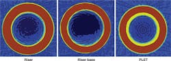
The company’s Integrity Management Engineering team chose to scan the flowline at the same three locations where subsea pulsed eddy current (PEC) volumetric measurements had been taken a year before. The first location was near the pipeline end termination (PLET), which would have the highest corrosion potential because it is the warmest part of the flowline. The second location - 3 mi (4 km) away from the first - was at the riser base, where liquid most likely accumulates. The third was near the riser itself, the section with the thickest wall pipe. Over time, soil had buried the flowline. To ensure clearance of the CT scanner, Hess dredged the soil around the three flowline locations using an ROV pump. This process took approximately one day to complete at each location.
The team took four scans at each of the three locations, each scan taking about 30 minutes to complete. The scans made visible everything from the heaviest steel density to the lightest gas mixture flowing within the pipe. Even the annular flow regime was evident in some of the images. All three pipe locations exhibited strong wall integrity and few corrosion issues. Wall thickness was slightly different in the three locations, with the PLET location experiencing a maximum of 14% wall loss in a localized area along the pipe’s inner circumference. Based on this data, the team concluded that there was no evidence of accelerated corrosion and that it was safe to extend the life of the field.
While most of the findings were positive, one image taken near the PLET revealed foreign material on the inside diameter of the pipe - a potential flow assurance issue. While CT scanning cannot identify the exact composition of a material, it did determine that the material’s density was lower than steel, but higher than any fluid expected to be found in the pipe. The team ruled out hydrate or paraffin because flow was occurring at approximately 5,000 psi (1,034 bar) and 200°F (93°C) near the PLET. Asphaltene and sand were also ruled out because the field has no history of either and the expected densities of asphaltene and sand would be slightly lower than the density of the buildup observed in the scan. However, several years ago, at the start of the field’s development, the team had identified a medium risk of scaling based on water sample analysis. The densities of scale supported this idea because they were consistent with the density of the buildup in the pipe.
One month after the scanning process, routine maintenance revealed a thin buildup on the choke as well. This buildup was isolated and sent to a lab, where it tested positive for barite or barium sulfate. The team concluded that the material inside the pipe was of similar composition.
To solve the buildup problem, Hess worked with a chemical vendor to select and inject an inhibitor downhole, to protect both the well and the flowline from future buildup. Ultimately, this successfully reduced the buildup and resulted in no new growth.
Only the second operator at the time to have successfully employed this technology globally, Hess found that employing CT scanning on the subsea flowline added value in multiple ways. Scanning the line without impacting production saved both time and money. The clarity of the scans made an accurate diagnosis of the problem possible, helping the company to identify the scale issue before it affected flow in the line. In addition, it confirmed that adding new, high-pressure wells to the brownfield flowline was a safe, value-adding decision. Awareness of the quality of the line saved future FD&A costs and protected Hess’ continued license to operate.