New composite riser design resists corrosion and fatigue
Roy Long
National Energy Technology Laboratory, US Department of Energy
The ultra-deepwater (greater than 5,000 ft or 1,500 m) discoveries in theGulf of Mexico, as well as offshore Brazil and Angola, present enormous development opportunities but also technical challenges. Specifically, the combination of ultra-deepwater and relatively large pipe diameter is outside current flexible pipe qualification scope, and imposes severe engineering challenges to both rigid and flexible pipe technologies.
For a flexible pipe solution, the combination of greater than 2,000 m (6,561 ft) operation depth and high design pressures (greater than 10,000 psi) will require technical innovations in current flexible pipe technology and rigorous testing to prove to customers that these new technologies are robust and durable.

To address those needs, GE, with the support of theResearch Partnership to Secure Energy for America (RPSEA), and with funding from the US Department of Energy’s National Energy Technology Laboratory, embarked on a development program to qualify flexible pipe with an internal diameter of eight inches for ultra-deepwater applications. The program is based on a novel hybrid flexible riser technology that is being developed and qualified by a combination of design, analysis of performance, material and subcomponent testing and finally, a field trial. Guidance for the qualification effort was obtained from the relevant sections of the standards and recommended practices from API and DNV. The discussion below covers Phase 1 of the project. Phase 2 will be discussed in a subsequent article.
The design concept consists of a hybrid composite and metallic/polymer flexible pipe with optimized mass per unit length for ultra-deepwater applications. In the GE design, the conventional metallic pressure armor is replaced with a carbon fiber reinforced thermoplastic composite pressure armor which is fully bonded to the thermoplastic barrier layer. In an effort to decrease overall programmatic risk and time to realize a qualified product, many of the existing layers and materials remain the same as those used in today’s qualified unbonded flexible pipe technology (e.g., the metallic carcass, barrier materials, metallic tensile armor, insulation and sheath). The details of the benefits and challenges of the individual layers of the design concept, as well as the design concept for the pipe’s end fittings, are summarized here.
Technology assessment
There exist two potentially capable, yet unqualified, commercialized technologies for the design requirements. The first potential solution would be to use conventional rigid metal piping typically applied as a steel catenary riser (SCR) or a top tensioned vertical riser system. Though the concept can be designed at relatively large diameters (greater than seven inches) to meet the working depth, design pressure and service requirements, it is at the expense of overall system and installation cost.
At depth, the pipe wall thickness necessary to support the collapse loads is significant and drives the overall pipe system weight to infeasible levels. In order to achieve a solution, a large number of buoyancy modules would need to be applied to the overall structure and would drive increased cost. The rigid nature of the pipe would also require many short lengths of pipe to be connected on site, which would compromise reliability, safety, and system cost. Lastly, to support sour service, lower strength alloys are required thus increasing the pipe weight per length and adding additional buoyancy requirements. In summary these challenges result in a system that although technically feasible, would require an unrealistic amount of material and deployment cost.
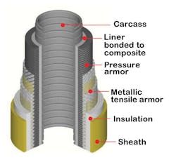
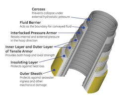
The second potential technology is unbonded flexible pipe. Conventional unbonded flexible pipe designs are a multi-layer construction based upon a thermoplastic pipe liner reinforced with metallic materials. A typical construction can be seen in the cutaway schematic of the flexible pipe. Each layer has a specific function, where the metallic layers include: a carcass for collapse resistance, hoop armor for pressure resistance, and tensile armor to carry axial tension and pressure endcap loading.
Unbonded flexible pipes are individually designed to the required field specification by optimizing the layer geometry and dimensions, adopting a modular approach which enables custom solutions to be delivered to operational requirements. For ultra-deepwater applications several lengths would likely be joined together because flexible pipes are delivered in continuous lengths defined by the delivery reel size or by a carousel equipped vessel. Typical reel capacity is approximately 3,300 ft (1,000 m), related to the typical lifting capacity of 300 metric tons (330 tons). Additionally, a modular approach for ultra-deepwater applications is necessary to achieve a dynamically stable system riser or flowline configuration and installation strategy.
Compared to rigid pipe, flexible pipe technology has several advantages. Because the directional strength can be tailored by changing the design of the individual layers, the tensile or collapse strengths can be optimized to achieve a lower mass per unit length. The resulting benefit is an overall lower pipe weight and decreased need for auxiliary equipment such as buoyancy modules. Secondly, because a continuous length of pipe (approximately 3,300 ft at seven inches) can be deployed from a standard reel, the installation logistics are simplified and the system costs reduced.
Despite those advantages, there exist several significant challenges for conventional flexible unbonded pipe. The primary challenge is that, despite the ability to optimize the layers, at 10,000 ft (3,000 m), the pipe weight and collapse loads are simply too large, and have pushed designs using current material technologies to their limits. Accordingly, though it does not need as many buoyancy modules, an unbonded flexible pipe would still incur significant deployment and materials costs due to the auxiliary measures required to compensate for the pipe weight.
Second, at the high design pressures required for these applications, the irregular surface of the carcass and pressure armor can cause further complications with the integrity of the barrier layer. Similarly, as the external surface of the barrier is reinforced by an unbonded but interlocked hoop layer, there is always a small gap which again is problematic on pressurization due to thermoplastic liner creep under the applied triaxial stress. Conventional design involves applying another functional layer; either an anti-extrusion layer to bridge the gaps or a sacrificial extrusion to prevent localized creep of the barrier. These extra layers inherently add extra cost to the manufacturing process and, by creating new interfaces within the structure, can also present more complex problems with permeated gases in the pipe annulus.
In summary, though it may be feasible to meet the technical requirements of the pipe technology using either rigid metal or flexible unbonded pipe, it will likely remain uneconomic due to the system and deployment costs required to achieve those solutions. For those reasons, and considering the enormous opportunity that ultra-deepwater resources represent, it is imperative that new technologies are developed that can achieve the technical requirements, at low enough risk, and at a feasible cost.
Technology gaps
Due to the challenges of the conventional commercialized technologies described in the previous sections, several companies have embarked on the development of alternative flexible pipe technology to meet the ultra-deepwater requirements. In all known cases the designs leverage the use of composite materials, whereby the design can be optimized to meet the targeted overall strength and mass per unit length requirements. In an effort to assess the potential advantages and challenges of these designs, they have been classified into groups depending on where the composite is used in the design. The remainder of this article will focus on the project’s subject matter experts’ consensus on the advantages and challenges of the proposed solutions, by the separate outline designs.
Design A
This is the metallic carcass, metallic pressure armor and composite tensile armor design. Its advantages include:
- Ability to optimize the winding angle to achieve desired tensile strength and secondary hoop reinforcement
- Leverages existing metallic carcass and pressure armor technology
- Reduced pipe weight per length.
Its challenges include:
- External placement of composite reinforcement exposes tensile layer to external damage
- Non-straightforward integration with standard end fitting flange technology, and high axial load transfer requirement.
Design B
This is the metallic carcass, composite pressure armor and composite tensile armor design. Its advantages include:
- Leverages existing metallic carcass and composite pressure armor technology
- Ability to optimize the winding angle to achieve desired tensile and pressure reinforcement
- Reduced weight per length.
Its challenges include:
- External placement of composite reinforcement exposes tensile and pressure armor layers to external damage
- Non-straightforward integration with standard end fitting flange technology, and high axial load transfer requirement
- Prevention of extrusion of liner through gaps in the unbonded reinforcement layer
- Additional ballast to sink and stabilize structure
- Currently proposed with unqualified thermosetting resins.
Design C
This is the no carcass, bonded composite pressure/collapse layer and metallic tensile armor design.
Its advantages include:
- Well-proven metallic tensile wire integration with standard end fitting flange technology meeting high axial load transfer requirement
- Ability to optimize the winding angle and layer structure to achieve desired internal pressure and collapse load reinforcement
- Currently proposed with qualified thermoplastic resins
- Metallic tensile armor improves damage tolerance by protecting internal composite layers
- Reduced number of functional layers and resultant interfaces
- Smooth bore liner for low pressure drop.
Its challenges include:
- Achieving a balanced internal and external pressure reinforcement
- Interface durability between the metallic tensile reinforcement and the underlying composite armor.
Design D
This is the composite pressure armor, composite collapse layer and composite tensile armor design.
Its advantages include:
- Ability to individually optimize the winding angle to achieve desired tensile, pressure and collapse reinforcement
- Lightest construction per unit length
- For a fully bonded design, straightforward inspection and low trapped permeated gas risk
- Well characterized thermoplastic liner materials
- Smooth bore liner for low pressure drop.
Its challenges include:
- External placement of composite reinforcement exposes tensile and pressure armor layers to external damage
- Non-straightforward integration with standard end fitting flange technology, and high axial load transfer requirement
- For an unbonded design, venting is necessary to eliminate trapped gas and decompression risks
- Gap reinforcement tape required to reduce the risk of thermoplastic liner extrusion
- Additional ballast to sink and stabilize structure
- Currently proposed with unqualified thermosetting resins (unbonded).