Fengjie Yin
Mike Campbell
2H Offshore
Imagine a small imperfection or crack on the inside of a high-pressure subsea connector. The imperfection may have initiated and grown in a number of ways, such as damage through operations, exposure to production fluids, or cyclic fatigue loads. When the connector is operated at very high pressures, such as 20,000 psi (1,379 bar), the pressure acts on the crack, prizing it apart. This extra load is called crack face pressure and can take the connector from a safe to an unsafe operating condition, possibly even causing connector failure.
Crack face pressure has historically been ignored. Note that the industry has not ignored crack face pressure through negligence or a lack of understanding; it was just rarely a design driver at lower pressures. Current design codes acknowledge that there may be cases when it should be considered, but there is limited guidance on when and how to account for it. The practice of fracture mechanics takes crack face pressure into consideration, and can be adopted when conventional design methods are no longer adequate. The goal here is to highlight potential gaps and risks of using more rigorous design methods for higher pressure and temperature applications.
Operators are looking to drill and develop deepwater wells with pressures and temperatures in excess of 15,000 psi (1,034 bar) and 350°F (177°C). These extreme high-pressure/high-temperature (HP/HT) wells have the potential for significant production rates but require a step change in the equipment and technologies used to develop them. The equipment is tested as the limits of design methods, metallurgy, corrosion resistance, sealing integrity and chemical make-up of components and systems are pushed.
As discussed, fracture mechanics is one tool that can be used in conditions where the use of more typical design methods results in an overly conservative design. The use of equipment-specific material data from tests, such as crack growth rates, fracture toughness, and stress-strain curve in combination with the more rigorous fracture mechanics methods can minimize this.
This approach has been adopted by the aerospace industry for quite some time. Its use in airplane design allows for material and weight to be carefully managed and more accurate predictions of airplane fatigue life to be determined. In oil and gas applications, the greatest benefits of fracture mechanics are seen in HP/HT applications, where high temperatures can have a big impact on material performance and high pressures result in large cross section thicknesses.
HP/HT equipment endures cyclic operations, and the cyclic loads can include pressure, temperature, and other external load cycles. For fatigue sensitive components used in HP/HT situations, it is insufficient to only check pressure containment in design. It is also necessary to calculate fatigue response for compliance with its functional specifications.
Fatigue response can be determined using either stress-cycle (S-N) or strain-life methods, or fracture mechanics design.
As per the guidance in API’s HP/HT Design Guideline API 17TR8, the traditional S-N or strain-life fatigue approach usually works well for structures without significant flaws. However, the S-N curves are usually tested from smooth, polished bar test specimens. The fatigue life is the sum of the number of cycles required to initiate a flaw and the number of cycles to propagate the flaw through the thickness of the specimen. If flaws already exist in a pressure-contained structure, initiation has already occurred, so the fatigue life of the structure is only flaw propagation life. In this case, using the traditional S-N or strain-life approach could give a non-conservative fatigue life prediction, so the more accurate fracture mechanics design should be selected for cases where fracture could result in catastrophic risk. Another advantage for using the fracture mechanics approach is that fatigue crack growth data is more readily available than S-N or strain-life data in corrosive environments.
The fracture mechanics method can also capture load sequence effects and changes in operating environment. For example, if the equipment is exposed to an extreme event such as a hurricane early in its field life, flaw growth will occur and shorten the structure’s life. The S-N method predicts the same life irrespective of when the loading occurs during the life of the structure.
While there are some reasons to use of fracture mechanics, there are also some reasons why it should not be used. For example, neglecting the effects of crack face pressure or assuming a worst-case flaw orientation are two common and acceptable approaches adopted in the design of equipment for lower pressure environments. Two case studies below demonstrate the effect these omissions could have on HP/HT equipment design.
Currently, the two main design codes being used in the industry for fracture mechanics assessments are API 579 and BS 7910. Neither code includes the complete effect of pressure loading on the crack face. While API 579 does incorporate the effect of crack face pressure loading in the calculation of the stress intensity solutions, the effects are not included in the calculation of limit load and thus, reference stress. BS 7910 does not give guidance on how to include the effect of crack face pressure in either the reference stress or stress intensity solutions although it does acknowledge that there may be cases where it should be considered.
The code guidance for flaw orientation is comprehensive, providing solutions for circumferential and axial flaws. However, in most equipment the dominant fatigue loading is in the axial direction resulted from tension and bending. So, circumferential flaws usually drive and axial flaws are often not considered.
Connector case study
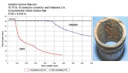
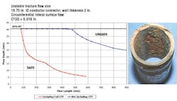
A conductor connector with an 18.75-in. inner diameter and wall thickness of 2 in. is subject to 20,000 psi internal pressure in an extreme event. Working off the premise that the connector has a small manufacturing imperfection, a crack growth analysis can be used to determine the life of the connector under cyclic fatigue loading, as discussed above in comparison to the S-N fatigue approach. The life is driven by two things: how quickly the imperfection will grow and at what size the flaw will cause rupture of the connector based on the unstable fracture.
The flaw size that will result in an unstable fracture is calculated both with and without crack face pressure. The plot shows a significant difference in allowable flaw size that will not go into unstable fracture. If crack face pressure was not considered in the assessment, the flaw could essentially grow through 80% of the wall before failure when the flaw length is 300 mm. Accounting for crack face pressure, a flaw with the same length will cause component rupture at just 25% of the connector wall.
Riser case study
A steel catenary riser (SCR) with an 8.625-in. outer diameter and wall thickness of 1.875 in. is subject to 20,000 psi internal pressure in an extreme event. Typically, circumferential flaws dominate because the fatigue loading and stresses in the axial direction dominate, which contribute to open up the flaw in a perpendicular orientation. However, in the case of a HP/HT SCR application, corrosion can result in pitting along the length of the pipe and these pits can grow into relatively long axial flaws. For applications in 15,000 psi and more, the higher hoop stress due to the high pressure in combination with crack face pressure acts to open up the axial flaws. As a result, axial flaws cannot be ignored.
The unstable fracture flaw size in the axial direction both with and without crack face pressure is illustrated in the bar graph. The result reiterates the importance of checking crack face pressure effects and also highlights the need to check both flaw orientations in HP/HT applications.
The use of fracture mechanics in HP/HT equipment design results in more accurate fatigue life estimations due to more in-depth assessments and incorporation of crack face pressure. The approach is being successfully used and is also encouraging designers to do additional due diligence and comprehensive engineering design, testing, and verification to meet the project requirements, which in turn increases safety and reliability.
