New technology attacks flowline and umbilical blockages
Allan Browne
Paradigm Flow Services Ltd.
Blockages within flowlines and umbilical cores present an on-going concern within the oil and gas offshore industry.Deepwater and cold water fields are driving ever longer and more complex tiebacks. Maintaining these supply and production conduits free from blockages is a high priority for operators. Unfortunately, either through change in producing conditions or simply through human error, blockages commonly develop within these systems.
Paradigm Flow Services' Find-Block and Pipe-Pulse technologies provide new alternatives to locate and remediate full-bore blockages in umbilical cores and pipelines. The dual system is capable of locating and releasing blockages that have resisted conventional means. Pipe-Pulse has freed blockages at distances of more than 10 km (6.2 mi) from a line access point.

Subsea flowlines and umbilical cores
There are two broad categories ofsubsea flowlines – steel pipe and flexible pipe – and both exist in a range of grades, capabilities, sizes, and costs. Many new pipes of both types have smooth cores to minimize friction losses, but both can still suffer from restrictions and blockages.
Blockages in flowlines can be categorized broadly as follows:
- Viscous organics: Wax (paraffin) and asphaltene build ups
- Hydrates
- Naphthenate/salt scaling
- Inorganic scale (e.g. calcium carbonate, barium sulfate)
- Mechanical blocks (e.g. stuck or stalled pigs).
Most subsea umbilical cores are made of either a Thermoplastic Nylon 11 (Polyamide) derivative or stainless steel pipe of various grades. There is a range of construction forms, but all have armor protection and a resin filling in the spaces between the cores.
Blockages in umbilical cores present potential risks to the ability to deliver chemical inhibitors to flowlines. Subsea systems are built with redundant cores that can be used if an operational core becomes blocked. A poorly maintained system rapidly depletes spares, inevitably leading to sub-optimal chemical injection. Production chemicals may be mixed and pumped together, due to a lack of cores, or the correct chemical dosage may not be pumped at all.
The main causes of such blockages are:
- Poor quality control of chemicals being delivered
- Incorrect handling and bunkering of chemicals offshore
- Poor procedures when changing the use of an umbilical core
- Human error
- Water ingress and chemical degradation before pumping subsea
- Subsea equipment failure.
Blockage location
Before trying to remediate any blocked system, it is desirable to establish the approximate location of the blockage. Blockage location techniques that use untethered pigs with acoustic, magnetic, or nuclear (radioisotope) based signal cannot be used in a pipeline system that is fully blocked. The lack of flow prohibits placement of these devices at the point of the blockage.
Sometimes the operator has an idea of where the blockage may be. However, where uncertainty exists, Paradigm's Find-Block system can be used. Find-Block sends a single, large pulse (or a controlled short series of pulses) of a suitable fluid (e.g. water/solvent/chemical) into the line. The distance to the blockage can be inferred from the time between sending the pulse and detecting its reflection. Special attention has to be paid to minimizing the influence of free gas in the line due to the dampening effect that gas has on the pulse(s).
The accuracy of the inferred distance to the blockage depends upon the accuracy with which the wave speed can be estimated. This, in turn, depends on the assumed fluid properties, which usually are not uniform along the line because of the presence of different fluids such as oil and water. When the fluid and pipe properties are known, the wave speed can be estimated. Sometimes, it is also possible to estimate the speed directly from measurements of the time-of-flight to and from a known component such as a valve at a known location upstream of the blockage.
Blockage remediation
Where no pre-installed provisions (intrusive intervention access points, heating elements, etc.) exist, remediation of completely blocked flowlines usually is limited to pressure manipulation or occasionally thermal (non-invasive techniques) or invasive techniques requiring cold tapping, hot tapping, or coiled tubing/jetting intervention if access can be gained. While invasive techniques are straightforward on single uninsulatedpipelines or flowlines, they can be challenging for insulated, concrete coated, buried flowlines, or for P-I-P and bundle systems. Subsea intervention requiring vessel, diver, or ROV support can be costly, and breaking containment for intervention can raise safety and environmental challenges which also need to be carefully managed.
Umbilical core blockage remediation
Pipe-Pulse is a new way to remediate subsea blockages using pressure pulses. Instead of simply increasing (or decreasing) the pressure and then holding it constant, a succession of pulses is fired along the line toward the blockage. The use of multiple, short-lived pulses "vibrates" the blockage, potentially triggering release mechanisms that are not triggered by sustained constant pressure.
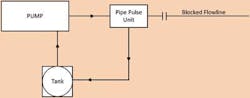
Pipe-Pulse operates on the principles characterized in the continuous flow loop. A positive displacement pump supplies the main Pipe-Pulse unit that includes a rapid acting valve, a programmable control system, and pressure sensors. Between pulses, the valve directs flow into a return loop with a large tank which supplies the pump. During pulses, it directs flow into the pipeline.
The pressure between pulses gradually increases as does the pressure during the pulses. Eventually the pressure approaches the maximum allowable for the pipe, and pressure is then released either continuously or during pulsation with modified control. The whole process is repeated as many times as necessary.
Once Find-Block is applied and the location of the blockage is known, the Pipe-Pulse remediation technique can be planned and executed. At the outset, it is important to determine the maximum strain to which the pipeline can be exposed. The operator usually will stipulate a maximum allowable operating pressure (MAOP).
Once the safe working pressure limits are known, a dedicated software package runs a series of simulation to determine the appropriate pulsing regime. The model can be used to predict pressures and strains along the whole of the pipe (up to the blockage) and to determine the maximum permissible base pressure to be allowed during pulsing. This data goes into the Pipe-Pulse control system to ensure that line packing does not exceed safe limits.
The Pipe-Pulse equipment enables control of:
- The base pressure in the line
- The differential pressure for a positive pressure pulse causing flow into the line
- The differential pressure for a negative pulse causing flow out of the line
- The maximum and minimum cycling pressures during line packing and unpacking
- The amplitudes of pulses
- The durations of pulses
- The time intervals between pulses
- Rates of change of pressure at the leading and trailing edges of pulses.
Pipe-Pulse inevitably causes line-packing. Line-packing causes the base pressure in the line to increase slowly until it reaches the MAOP, whereupon the control system begins to "reverse pulse." That is, "negative" pulses are applied causing line-unpacking and bringing the base pressure down to a predetermined minimum value. The whole process can then be repeated and, in principle, can be repeated indefinitely.
A blockage-clearing operation might cycle in this continuous manner for many days before a blockage begins to move. Based on experience to date, however, success is often achieved within a matter of hours.
Some limitations exist for using Pipe-Pulse. The method is not as effective if the line contains large pockets of free gas. Pulses are greatly damped by such pockets and rates of change of pressure are damped even more. Many lines with multiple ID changes cause some dispersion of pulses, even in the absence of free gas pockets.
The likelihood of the successful removal of blockages generally decreases as the distance between the pulsing equipment and the blockage increases. The effective feasible distance tends to increase with increasing pipe diameter and with decreasing sources of damping.
Field case studies
One Pipe-Pulse field application was in a 150-mm (6-in.) diameter flowline and another was a 12.7-mm (1-in.) diameter umbilical. In both cases, the operator was unsuccessful with conventional methods to unblock the lines.
In the first case, a 150-mm diameter flowline was blocked in a central North Sea oilfield about 200 km (124 mi) east of Aberdeen. The blockage was in a long pigging loop, and both ends were located using the Pipe-Pulse time-of-flight method. This showed the blockage was short and that it was about 11.4 km (7 mi) from one end of the 31.9-km (20-mi) long loop. It was decided to attempt to move the blockage in the shorter direction even though it would require sending pulses in the longer direction.
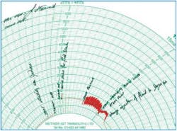
Pressure records measured at a sensor in the line, between the Pipe-Pulse equipment and the blockage, show time increases clockwise and pressure in radial positions. Two broad periods of activity were seen. The first was the blockage location test and the second was the blockage removal process. Between these periods, the pressure was initially about 100 bars (1,450 psi), but decreased slightly over time. The cause of the decrease cannot be known with certainty, but it is likely that a small bypass through or past the blockage was created by the large pulsing used to locate the blockage.
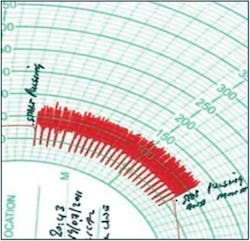
In the active period of continuous pulsing, the pressure fluctuated strongly and the line-packing and un-packing behavior was recorded. That is, the mean pressure gradually increases and then decreases. The mean pressure then fell strongly, as did the amplitude of the fluctuations. This indicated that flow had become possible through the blockage. The pulsing process was stopped and a period of nominally steady flow of approximately 500 liters/min (132 gal/min) was started. When this high rate of pumping was stopped, the pressure reduced strongly, indicating that a circulating path had been created. Creation of a useful flow path through a blocked span is key to operators, who then have a range of methods to remove the remaining restriction. Once this flow path was achieved, control was returned to the operator.
The second case study concerns a 12.7-mm diameter wax inhibitor line. The line was rated to 340 bar (4,641 psi), and previous testing at that level did not remove the blockage. The line was 15.95 km (10 mi) long. The client knew where the block was based on previous investigation.
The line was packed to 80 bar (1,160 psi) and then pulsing commenced, with maximum pressures far below 340 bar. In this case, the pressure chart shows no obvious signs that the blockage was free, but a different message was given by the Pipe-Pulse equipment because the fluid level in the return loop dropped continuously. This implied that either the blockage was moving or there was a leakage path through it.
Accordingly, pulsing was stopped and the pressure decayed continuously, indicating that a flow path did, indeed, exist. An additional 2,000 liters (528 gal) of solvent was pumped into the line (three times the line volume) and the line was handed back to production.
Testing
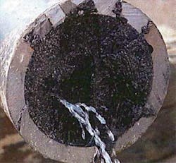
In recent onshore testing, blockages were created in a 215.9-mm (8.5-in.) ID pipeline. Five tests were performed against blockages: one single hybrid, two single bitumen blockages, and two gel/water/hybrid blockages.
The tests showed that Pipe-Pulse could create a flow path by cohesive breakthrough in bitumen and hybrid blockages. It also demonstrated that Pipe-Pulse could succeed where pressure alone could not.
Additionally, testing demonstrated that further pulsing can create large flow paths once initial breakthrough is achieved. Pipe-Pulse will extrude asphaltene/bitumen blockage material from the end of a spool piece where a gap exists between the spool end and a blind flange. This learning will enhance further blockage remediation design and operations.
In addition to these tests, verification testing confirmed the Paradigm STATIS transient model.
References
Mackenzie, H and Vardy, AE (2012) "Use of pressure surge for unblocking hydrocarbon pipelines", 11th International Conference on Pressure Surges, BHR Group, Lisbon, Portugal, Oct. 24-26, 2012.
Deepstar V Project 2003, "Pipeline Blockage Remediation Strategies for Long Offset Subsea Flowlines and Pipelines".