Early FLNG projects deal with technical and execution challenges
Andy Loose
Chris Caswell
Marlowe Bentley
Rebel LeBoeuf
KBR
Richard D'Souza
Granherne
Floating liquefied natural gas (FLNG), an ambition of the offshore industry for many years, is now well on its way to becoming a reality, as the first FLNG projects sanctioned are in advanced construction. Delivery of an FLNG project requires combining the experience of the onshore LNG industry with that of the FPSO industry. A successful team must consist of individuals with LNG experience and FPSO experience. It is also essential that FLNG project teams understand the aspects of FLNG that are unique from onshore LNG facilities and traditional FPSOs.
A huge proportion of the world's offshore gas discoveries are located in under-developed or remote regions of the globe. Lately, the economics of some onshore LNG plants are becoming increasingly challenged, as suitable gas fields have become more remote and project infrastructure has become difficult to construct. When these infrastructure and logistics issues result in high costs and high execution risk, there is an opportunity to bring gas to market with an FLNG facility. Even when the country infrastructure is mature, FLNG may also be a good solution.
There are many opinions as to why it took so long for the first FLNG projects to be sanctioned. These opinions commonly involve risks large enough to stall concepts in the appraisal phase. Every risk is a potential cause for concern, but technical, commercial, and execution risks are present in all large industrial projects. The key to a successful project is the identification and mitigation of these risks, which is achieved by a solid project execution plan. Execution planning anticipates risks by applying the appropriate lessons of the past to new concepts and situations.
Similar to FPSOs and onshore LNG plants, FLNG concepts vary widely, and no two projects will be exactly alike. FLNG projects will vary in capacity, use different technologies, and will be based on different hull concepts with different containment and LNG offloading systems. They will also be subject to variations in feed gas composition, rate, and pressure.
Greater scale and complexity
Although traditional FPSOs can have sizeable gas processing facilities, the liquefaction plant adds considerable equipment and complexity. A "standard" feed gas flow rate of 500 MMcf/d would produce between 3 million and 4 million metric tons per year of LNG.
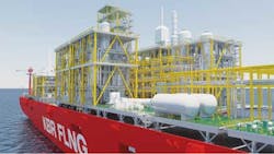
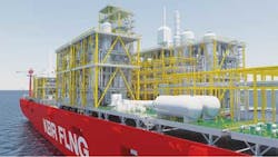
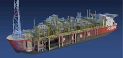
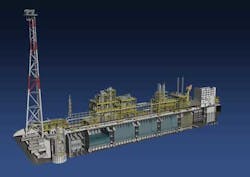
The key aspect in developing FLNG is the size of the hull necessary to make the project financially viable. The largest FPSOs have a length of about 300 m (984 ft), width of 60 m (197 ft), and topsides weight of 35,000 metric tons. A mid-size FLNG facility with a capacity of 2.5 million tons per year may have hull dimensions of 380 m (1,247 ft) by 66 m (217 ft) and topsides weight of more than 40,000 metric tons, larger than any current FPSO. A large capacity FLNG could have dimensions of up to 500 m (1,640 ft) by 75 m (246 ft) and topsides weight of much greater than 50,000 metric tons.Shell's Prelude FLNG will push the boundaries at dimensions of 488 m by 74 m. This increase is due to both the topsides footprint and the liquids storage volume required. At these dimensions, the choice of dry docks for fabrication is very limited.
Another difference between FLNG and an FPSO is the amount of topsides production equipment required. The liquefaction of natural gas requires a highly purified feedstock. Production gas sent to the liquefaction process must be treated for CO2 (to <50 ppmv), water (to < 1 ppm), H2S (to < 4 ppmv), and mercury (to < 10.0 ng/Sm3), and all C5+ components that would freeze during refrigeration must be removed. In addition to LNG, storage of condensate and possibly LPG may be required. Although LPG and condensate add complexity to the FLNG project, the liquids strongly improve the project economics.Technical challenges
Many of the technical challenges relate to hull motion and its effect on process and equipment. The FLNG facility typically must remain moored on location for at least 20 years without ever returning to port. It must be designed to operate in extreme weather environments, such as cyclone-prone northwest Australia. Marinization of the equipment, which allows acceptable performance under these conditions, is one of the key design challenges.
Process technology
Operators have differing opinions as to which liquefaction process technologies are best suited to FLNG. These technologies include:
- Inert refrigerant expander technologies (nitrogen processes)
- Dual expander technologies (nitrogen and methane)
- Single mixed refrigerant technologies (SMR)
- Dual mixed refrigerant technologies (DMR)
- Traditional baseload technologies such as Air Products' C3MRTM and ConocoPhillips' Optimized Cascade.
Objectively, all available technologies could be applied for FLNG. Each provides a different balance between cost, availability, operability, efficiency, footprint, weight and safety for use offshore. However, the weighted evaluation criteria applied during the liquefaction process selection study will narrow the options. Regardless of the liquefaction process technology, successful FLNG execution lies with equipment selection and design.
Equipment
In general, FLNG equipment will be larger and heavier than that of an FPSO. There are some basic rules for equipment layout that are derived from decades of FPSO experience that apply for an FLNG to limit the impact of hull motion. Some of these include: installing perforated baffles/proprietary internals inside process vessels and tanks to dampen liquid turbulence; the design of gravity drain piping and flare headers to account for vessel motion; consideration of hogging and sagging of the hull deck on equipment supports and piping flexibility; and the design of liquid level instruments.
An FLNG unit might have a number of tall vertical columns in the acid gas removal unit (AGRU) and fractionation unit, and tall exchangers in the liquefaction unit. The performance of these tall columns/exchangers is critical to maintain availability and production, hence the need to limit permanent static tilt and limit hull motions, particularly roll.
Plant availability is an important issue for FLNG. The time taken to restart a liquefaction system and achieve on-spec LNG is much longer (12-24 hours) than re-starting a traditional FPSO. Plant trips must therefore be avoided.
AGRU and dehydration equipment
The AGRU contains one of the largest and heaviest vessels in an LNG facility, the AGRU absorber. The design specification of the AGRU is much tighter than that for typical FPSOs and is necessary to prevent freeze-out of CO2 and H2S in the downstream cryogenic equipment. Under static tilt or dynamic roll, the AGRU system could suffer sub optimal-performance by insufficient solvent contact with the natural gas. As an example, if 1% of a feed gas with a CO2 concentration of 2% slips through the absorber without contacting any liquid, this would represent a minimum CO2 in the treated gas of 200 ppmv – four times the design limit of 50 ppmv.
Liquefaction equipment
The specific equipment within the liquefaction module(s) is a function of the process technology and the train size. In particular, this includes the refrigerant compressors and drivers (turbines or motors), the main cryogenic heat exchanger (MCHE), companders and possibly hydraulic turbines. The design and supply of the MCHE depends on the selection of the liquefaction process technology but will be either a plate fin heat exchanger (PFHE) or a spiral wound heat exchanger (SWHE). Both are used for onshore LNG projects but are currently unproven offshore at the desired size and scale.
The train size is a function of the selected liquefaction process technology and power supplied by the compressor drivers, although the scalability of each technology has its practical limits. Dual expander schemes typically have a capacity of up to 1.2 Mt/a per train so two trains are required for a mid-sized facility. A DMR scheme will have a capacity of about 3 Mt/a per train. While multiple FLNG trains will provide increased availability, the increased equipment count will affect the overall maintenance program. Commercially, it may appear that bigger is often better or more economic, but the design and fabrication of the topsides modules with larger equipment and piping is an added challenge which must be considered.
Onshore liquefaction systems have used large industrial gas turbines as mechanical drivers. Most FLNG projects are considering aero-derivative gas turbines, although some schemes use steam turbines or electric motors. Aero-derivative gas turbines provide high power per unit weight; although they have lower gross power output than industrial machines, aero-derivative machines are well suited for small- to medium-sized LNG trains.
Liquid storage and offloading
Although LNG carriers have been safely transporting LNG for over 40 years, these carriers operate in either a near empty or near full condition. For FLNG, the LNG cargo containment system (CCS) must operate with tanks in any state of fill. For storing large volumes of LNG, the choice for the CCS is primarily the proprietary self-supporting prismatic type B (SPB) tanks licensed by IHI or the membrane systems licensed by GTT. Moss type storage, common for LNG carriers, is usually not considered, due to the encroachment of the upper hemisphere of the LNG tank where the topsides is typically located. The membrane system has dominated the LNG carrier market in recent years; however, for FLNG applications, there have been concerns about the long-term structural integrity of membrane tanks due to sloshing. This risk has been largely mitigated by designing a double row of smaller tanks with a central cofferdam to reduce the LNG sloshing loads.
The design of the LNG offloading system for ship-to-ship transfer has been one of the main challenges in the development of FLNG. The main choices are traditional side by side (SBS) offloading using rigid articulated loading arms or dynamic hoses, or a tandem operation using either articulated loading arms or hoses.
The SBS method using rigid arms has been preferred by the projects sanctioned to date. However, the relative movement between the FLNG and the LNG carrier is far more challenging for the rigid loading arms than typically seen for onshore projects. As a result, FLNG offloading operations are limited to sea states of up to 2.5-m (8-ft) wave heights. The rigid arm suppliers have worked extensively on their designs to demonstrate their suitability and robustness in this new environment.
For tandem loading concepts, newer technologies using mechanical arms or flexible hoses connected to bow-mounted carrier manifolds would allow offloading operations in waves up to 5 m. However, LNG carriers would need to be fitted with bow-mounted manifolds. Additional testing of the tandem loading hardware is still needed, but in the long term this system may be a more robust solution for FLNG.
Topsides layout
The topsides layout presents new challenges because of the size of the equipment and piping for FLNG. The overall size of the hull is driven by either the storage requirements or the topsides footprint, and the optimum is when both are balanced. For FPSOs, typical module weight may be up to 2,500 metric tons for easy installation at the fabrication yard. For FLNG, there is a preference to design larger modules to maximize the process system in a module for the benefit of pre-commissioning, hook-up, integration, and commissioning activities. In some FLNG designs, modules have grown to 10,000 metric tons. This weight growth has forced shipyards to invest in new floating cranes and alternative installation methods. Shipyards and fabricators should be engaged early with topsides engineers to select the best solution for the project.
Some of the refrigerant piping can be up to 1,500 mm in diameter, excluding the insulation. Add in the complexity of the pipe stressing and supports for cryogenic lines, and the space requirements for piping are significant.
Hull and marine systems
The design of the hull, risers, and turret/mooring system is a significant challenge regardless of the specifics of topsides processing. In most cases, an FLNG hull will be larger than an LNG carrier or FPSO. The hull design must accommodate a much greater topsides weight and provide requisite hydrostatic stability to minimize motion.
FLNG concepts to date have generally adopted an internal turret solution around which the facility weathervanes. The use of a turret, whether external or internal, benefits LNG offloading by increasing availability. In the case of SBS offloading, beam seas are avoided, resulting in reduced roll. For tandem LNG offloading, allowing the LNG carrier to weathervane with the FLNG unit simplifies the hook-up and offloading process. The size of the turret is a function of the water depth and the number of risers. For an FLNG project, the number of risers is usually limited; to date, the turrets and swivels are within the industry's design and manufacturing capabilities.
The role of safety
At an absolute minimum, FLNG must carry the safety principles, philosophies, and practices developed from the FPSO industry. To advance FLNG to fruition, safety cannot be compromised by poor analysis, lack of operational experience, or the ignorance of the true risks of LNG production, storage and offloading offshore.
Safety is a sensitive subject for FLNG because there is no precedent. FLNG introduces a whole new set of safety considerations compared to an FPSO because of the complexity of design and operations. Some of the key safety considerations to be managed include cryogenic liquid spills, vapour dispersion, storage and handling of refrigerants and LPGs, and operations during LNG offloading. Unlike FPSOs, there is no definitive set of rules or criteria that can be applied to deem a facility safe. The project has to demonstrate that all reasonable measures have been taken to mitigate safety risks and that the residual risks are acceptable.
Cryogenic liquid spills and cold vapor releases can quickly generate very large gas clouds which, if ignited, could generate blast loads much higher than typically seen on FPSOs. The use of safety gaps between critical modules is considered the best method for blast pressure mitigation. The other concern related to cryogenic spills is the protection of the hull and topsides module structure. Drain systems must be designed to drain the LNG to a safe location, which may be directly overboard. Specialized coating may be used in combination with passive fire protection to protect the hull deck and primary steel.
Project execution
In the early days of FPSOs, technical complexity was underestimated and schedules were overly optimistic, which led to a number of delayed projects and cost overruns. During execution, the technical complexity of integrating a tanker design with a topside design emerged quickly. Many changes were required to ensure the overall system would work and that the interfaces would match. Different regulations for shipping and topsides design further complicated integration. The two most common execution problems were the carry-over work from shipyard to topside/integration yard and weight growth of the topside facility.
FLNG engineering teams face similar first-of-a-kind execution challenges, and it is critical that lessons learned from FPSO and LNG projects are fully considered. Cross-training will be required so that those with LNG backgrounds will understand offshore constraints, and those with offshore backgrounds will understand the issues around liquefaction, storage, and offloading. An FLNG project execution team must have a strong focus on identification, planning, and solving the physical and technical interface issues between the hull and topsides.
Fabricators also face new challenges compared to traditional FPSOs. Large-bore stainless steel piping, cryogenic pipe supports, and cryogenic insulation involve different fabrication practices and skills.
For FLNG topsides, there is little historical data to benchmark weight and cost estimates. However, the ability to benchmark designs and estimates against historical data from recent large FPSO projects provides some confidence in cost forecasts and schedules for FLNG. Lessons can be learned from the design and fabrication of large process modules completed for onshore LNG projects. These modules are more comparable than many FPSO modules because of their size and type of equipment.
FLNG is pushing the boundaries of scale and complexity. The industry has risen to the technical challenges, and risks have been mitigated, allowing the first FLNG projects to be sanctioned. As FLNG projects advance, new issues will arise. A properly structured execution plan incorporating lessons from both FPSO and complex LNG projects – and from the emerging FLNG projects – can lead to commercial success.


