Prototype AUV advances deepwater inspection capabilities
Roy Long
National Energy Technology Laboratory
US Department of Energy
Under the Energy Policy Act of 2005 (Sec. 999), the DOE's National Energy Technology Laboratory (NETL) is charged with funding and implementing programs aimed at developing the nation's deepwater, unconventional, and mature assets in line with projected energy needs for the 21st century. The Research Partnership to Secure Energy for America (RPSEA) is a key component of this effort.
Administered through a nonprofit organization, RPSEA emphasizes governmental, private, and academia partnerships to develop medium to long lead time solutions to challenges in deepwater and unconventional resources development.
Recent events in the Gulf of Mexico have led to even greater emphasis on safe and environmentally benign technologies within the program for deepwater development, leading NETL to impose a safety and environmental sustainability overlay on its ongoing Sec. 999-funded R&D.
The focus here is the results of one such effort, an autonomous underwater vehicle (AUV) designed to inspect deep and ultra-deepwater structures and seafloor anomalies.
Research project
A research project directed by Lockheed Martin has developed and is testing an AUV capable of sophisticated equipment inspection and monitoring in deepwater. The research project, with funding from NETL, recently tested the AUV on structures in the Gulf of Mexico.
Deepwater inspection challenges
Management of deepwater fields requires routine general inspection of critical infrastructure. To date, the only means of conducting such inspections has been through the use of remotely operated vehicles (ROVs). Deepwater ROV spreads are big and heavy, requiring large support vessels with dynamic positioning capability and a significant number of personnel at sea. AUV capabilities have been improved to the point that they can now conduct unassisted detailed inspection of subsea facilities. Benefits of autonomous inspection include:
- Reduced cost of operations
- Faster inspection
- Automatic change detection
- Geo-registered inspection data
- Simultaneous operations from a single support vessel
- Large standoff distances from the facility being inspected
- Increased operations safety
- Reduced environmental impact
- Reduced specification requirements on support vessel
- Smaller deck footprint
- Dynamic positioning not required
- Fewer personnel at sea
- Reduced mobilization costs
- Faster response to emergency inspections.
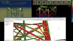
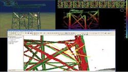
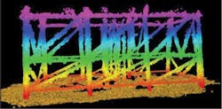
The operational concept is to have an AUV autonomously inspect an offshore oil and gas platform with minimal user input. The user simply chooses the platform facility, and specifies how much of the platform is to be inspected using a command and control user interface. The AUV autonomously plans the inspection path around the platform, executes this path to collect sonar data, builds a 3D model of the platform in real-time, and executes change detection to identify anomalies.
Feedback of the path of the AUV and the detected anomalies is provided to the operator in near real-time. The in situ 3D model of the platform constructed from the current inspection, along with 3D models of the anomalies, are available to the operator upon recovery of the AUV. These models can be exported to a variety of formats to address the needs of individual users. The Offshore Platform Inspection System (OPIS) is composed of three primary subsystems: the Marlin vehicle system, an autonomous perception system, and an autonomous response system.
The integration of the major autonomy components is achieved via well-defined interfaces. These allow for the independent development of key autonomy technologies as well as the rapid insertion of plug-and-play capabilities. These interfaces follow the ASTM F25411 draft autonomy standard where applicable. This standard defines a messaging interface in terms of message content without regard to transmission protocols or mechanisms. Initial testing and development of the integrated system was performed in a simulation laboratory which provides vehicle dynamics, 3D imaging sonar data, and inertial navigation data. This lab testing addressed many integration issues early in the integration process, thereby reducing the need for expensive sea trials.
Vehicle system
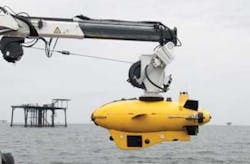
The Marlin AUV is a mature Lockheed Martin product which has been used on multiple missions. The system consists of the AUV; an operations and maintenance (O&M) van; a launch and recovery system; and a shipboard cradle assembly.
The O&M van, launch and recovery crane, and the shipboard cradle assembly is each configured with standard 20-in. ISO fittings, which simplifies shipping and shipboard mounting. Mobilization is straightforward, and the entire system can be installed in three lifts. This simple and efficient configuration is operated and maintained by three people: a vehicle operator, a crane operator, and a deck hand. Marlin's patented autonomous underwater homing capture and lift provides a robust and simple approach to vehicle recovery, unlike the sometimes risky and weather-dependent surface recovery methods. The small footprint of the AUV system also allows for deployment on a smaller, less expensive vessel when compared to a standard ROV spread.
Data collection and processing
The autonomous perception system transforms the sensor data into information. Autonomous perception technologies have been demonstrated in the air and ground domains using ladar point clouds. These are similar in format, though not in quality, to the data available from a 3D imaging sonar. Lockheed Martin autonomous response and perception technologies are modified and adapted to the undersea environment to achieve the goals of the OPIS.
The perception system is responsible for processing the 3D imaging sonar data to generate 3D models of the offshore oil and gas platform. During structural surveys, the sonar is compared to a prior model of the platform to detect changes. Because of the uncertainty in the vehicle pose (and hence the sensor pose) provided by the navigation unit, the sonar data must first be properly aligned to the prior model before it is assembled into a changed model. This alignment is performed using a random sample consensus (RANSAC) over the sonar points to find the pose adjustment that aligns the largest number of sonar points to the model. The prior models are built using this same alignment approach, but incoming sonar data is aligned to the model built so far from the earlier data. This process is typically guided by a human operator to insure the quality of the resulting model.
Navigation
Autonomous response is responsible for guiding the vehicle safely through the inspection mission. The response system provides mission planning, high-level guidance and contingency detection, assessment, and response capabilities for the AUV. Mission planning is separated into two phases.
First, a high-level planner narrows the user-defined search area to a tractable planning space while ensuring each section of the platform is visible to the sonar. Then, a detailed planner generates an optimized trajectory for the vehicle which ensures maximum sonar frustum coverage while maintaining a desired distance from the platform. (In 3D computer graphics, the frustum is the region of space in the modeled world that may appear on the screen.)
The detailed planner accounts for vehicle constraints and sea currents to ensure that the planned path is dynamically feasible. The high-level guidance module directs the vehicle along the planned trajectory. This module attempts to minimize deviation from the path while maximizing time spent with the vehicle in the planned orientation along the path. The former is needed to ensure the vehicle maintains the desired distance from the platform, while the latter is required to ensure that the planned sonar frustum coverage is achieved.
Even with effective planning and guidance, unexpected events can occur. The contingency detection system identifies these events. This module is decoupled from the guidance and navigation software, and allows for leveraging tested and proven software components from existing systems. The contingency detection, assessment, and response system is based on the Lockheed Martin Mission Effectiveness and Safety Assessment (MENSA) system. A separate contingency assessment and response system provides the ability to implement multi-tiered responses to detected contingencies.
Tests and field trials
Integration of the three primary OPIS components - vehicle, autonomous response system, and autonomous perception system - was initially evaluated in the simulation laboratory. Performance of the autonomy algorithms was validated on tactical hardware in a low-risk, reduced-cost environment that allowed for robust verification and testing of the system before offshore trials. This allowed the team to proceed offshore with increased confidence that the system would perform as designed, with a reduced risk of losing or damaging the vehicle or structures being inspected.
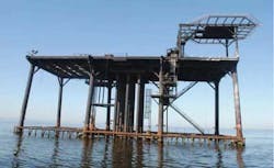
The team also performed verification and validation exercises in the Gulf of Mexico using decommissioned offshore oil and gas platforms. These exercises prove that the system is capable of quickly, accurately, and safely completing a structural survey of an offshore oil and gas platform with minimal operator interaction and oversight.
Through these exercises, the team verified the system's ability to build a model of a platform and detect anomalies in an operational environment. This combination of technologies is an improvement over current state-of-the-art offshore inspection capabilities.
The Marlin's inspection capabilities continue to be improved. Future capabilities will include:
- Level II platform inspection
- Inspection of risers, mooring lines, touchdown points, and strakes
- Pipeline inspection including position, crossover, scouring, and corrosion potential
- Wellhead, PLET, PLEM, flowline and UTA inspection, leak detection, thermal and debris survey
- Incorporation of a high-resolution laser inspection system capable of generating highly precise stick diagrams suitable for CAD/CAM software to generate "as built" drawings. (If this capability had been present during Macondo, an accurate drawing of the wellhead, suitable for capping stack design, could have been made in one day.)
NETL deepwater portfolio
This project is representative of the R&D work being undertaken via the Section 999 Program to ensure safe and efficient development of the nation's deepwater and ultra-deepwater assets. Altogether, NETL has over 30 active deepwater and ultra-deepwater projects in various stages of progress, with another 17 to be added from the 2012 program. Proposals for research under the 2011 Ultra-Deepwater Program are in negotiations following awards. Requests for proposals (RFPs) for the 2012 Ultra-Deepwater Program have been posted on RPSEA's website atwww.rpsea.org. Current information for the 2012 RFP solicitation can be accessed on the Current Request for Proposals page under the "Business with RPSEA" menu button. Proposals for Round 1 of the 2012 Ultra-Deepwater Program R&D projects are due on Sept. 25, 2013.
