Study explores all-electric subsea HIPPS reliability and maturity
Craig W. Lamison
Granherne, a KBR Company
Khalid Mateen
Total
With subsea developments moving to longer tiebacks and deeper water, all-electric architecture has potential advantages over the conventional electro-hydraulic system: lower cost resulting from doing away with the hydraulic umbilical, reduced and easier maintenance, less environmental impact, and simplification of topsides. All-electric equipment is now becoming available for subsea hydrocarbon development activities to allow this.
Use of the all-electrical architecture in developing a high-pressure field, however, requires a reliable subsea autonomous all-electric High Integrity Pressure Protection System (HIPPS), to allow a lower design pressure than the shut-in wellhead pressure for the downstream facilities. This pressure de-rating of infrastructure could allow further cost savings.
Recently, research was undertaken in a DeepStar study to assess the Safety Integrity Level (SIL) achievable for an all-electric subsea HIPPS. Where data was scant, due to the immaturity of the technology, the assessment was based on conservative assumptions. The work showed that an SIL 3 is achievable for an all-electric subsea HIPPS. This is in the same range as that of electro-hydraulic systems for similar architectures.
The work evaluated the probability of loss of containment in a HIPPS Utilizing System (HUS) with multiple wells and HIPPS. It covered both electro-hydraulic and all-electric HIPPS based on the probabilities of failure on demand (PFDs) developed in the SIL assessment. This evaluation determined the probability of loss of containment for several HUS concepts to identify how the PFDs previously calculated affect typical subsea tieback designs using multiple HIPPS.
The evaluation showed that common cause failures significantly influence the probability of loss of containment. Reducing common cause failures by employing different equipment can reduce the probability of loss of containment by a factor of two.
As common cause failures are independent of the number of HIPPS, smaller HIPPS could be used at each well rather than one large HIPPS at the manifold. The study also found a lack of prototype all-electric actuated valves and associated reliability data at the higher pressure ratings where HIPPS are most useful.
Although not addressed in detail in this article, the work also identified gaps to be addressed to bring all-electric HIPPS technology to the same technology readiness level (TRL) as conventional electro-hydraulic HIPPS.
A number of industry documents provided guidance. These included API RP 17O, Recommended Practice for Subsea High Integrity Pressure Protection Systems, and API Specification 14C, Recommended Practice for Analysis, Design, Installation, and Testing of Basic Surface Safety Systems for Offshore Production Platforms.
IEC 61508, Parts 1 to 4, Functional safety of electrical/electronic/programmable electronic safety-related systems and IEC 61511, Part 1, Functional safety—Safety instrumented systems for the process industry sector were used for relevant calculations.
Findings
The study concluded the following:
- An all-electric autonomous subsea HIPPS is capable of meeting SIL 3 requirements and safely replacing a hydraulic HIPPS.
- Such a HIPPS will require varying levels of development to reach a TRL suitable for deployment. The authors expect that a 5 to 7-in. HIPPS in the 5,000 to 10,000 psi pressure class could be developed, tested, and ready to deploy in an offshore subsea test or a non-critical application in as little as two years. A larger 9-in., 15,000-psi system would take longer, perhaps five years.
- Hydraulic technology has a clear lead at this point, having been deployed for over a decade in subsea HIPPS as well as far longer in tree and manifold applications.
- Many of the components on a HIPPS are already electric - sensors and logic solvers for example. Little if any qualification will be necessary for these. The primary effort for these components will be integration into an all-electric HIPPS.
- The electric actuators and associated components, particularly ones suitable for large-diameter, fail-safe final element valves, are the critical components requiring further qualification.
- Electric fail safe (spring return) actuators make use of generally accepted methods to maintain the valves in the open position with minimum power input, generally less than that required for a 100 watt light bulb. Higher power requirements are required to open the valves but power requirements are generally modest.
- The electric actuators must be mated to suitable valves. Existing hydraulically actuated gate valves as used subsea for HIPPS or christmas trees are expected to be suitable with little modification for use with electric actuators. This needs to be demonstrated and qualified since the two components must work seamlessly together. Likewise the electric actuators will require a suitable motor controller, which, if not packaged with the valve and actuator, will require separate qualification.
- An all-electric HIPPS faces similar limitations for a given facility as those for hydraulic HIPPS. However, hydraulic HIPPS technology has a wider range of available sizes and pressure ratings, up to at least 5-in., 15,000 psi or 10-in., 10,000 psi. Hydraulic technology entails less uncertainty based on field experience, so subsea testing before operational deployment should not be required.
- Manufacturers believe electric actuator technology, mated with larger diameter and higher pressure valves, to be fully scalable from current technology. No feasibility issues were identified in this study to contradict this assertion. However, without further design and development, factors such as installation size and weight may become challenges for both electric and hydraulically actuated large-diameter and/or high-pressure HIPPS.
- Further qualification efforts should concentrate on electric actuators, their components, and the appropriate matching valves. Other components and system integration are of less importance in bringing an all-electric HIPPS to a deployable TRL.
- Multiple vendors should be involved in further qualification efforts to provide diverse equipment, which can help reduce common cause failures if used in the same system.<
- Higher pressure valves and actuators are needed for HIPPS applications to overmatch the lower pressure system they protect. This should be an area of focus for further qualification efforts.
Capabilities and configuration
In addition to the above requirements, HIPPS valves are assumed to have zero leakage at the factory acceptance test and site integration test stages of project. If valves should leak in service, it is expected that a regulatory waiver to continue operation will be required. The leakage criteria used to examine the consequences of leakage is for underwater safety valves (USVs) from API Specification 14C, Table D-1. It allows a leak rate of no more than 400 cc/min.
Operational requirements
In order to evaluate the SIL rating of an all-electric HIPPS, definition is required for design of the major HIPPS components. HIPPS are usually custom designed on a project-by-project basis and a PFD calculation performed to confirm that the design meets project requirements. For this study, a basic representative design was proposed, recognizing that variations are possible.
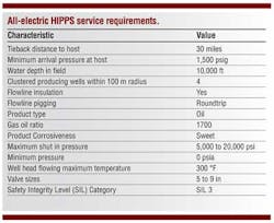
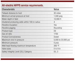
The HIPPS design for the study has the necessary operational functionality to accommodate the following procedures:
- Reset and restart after an autonomous shutdown
- Execution of sensor, logic controller, and leak tests
- Chemical supply to ensure flow assurance for shutdown and start-up.
Operators or regulators may require testing methods more stringent than those proposed here, which assume testing the logic solver and sensor response separately rather than as a single system with the valves. To test as a system would require an additional test valve just downstream of the final element valves. This valve would be outside the safety function and would not affect the reference design or the calculations in this study.
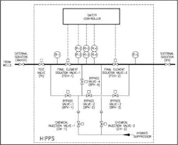
HIPPS description
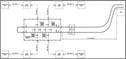
The proposed design comprises universal HIPPS components: redundant pressure sensors, logic solver, operational capability piping, and final element valves and actuators. Often, additional sensors, sometimes even other additional components such as valves and controllers, are used to increase HIPPS operational life. Components should be field replaceable when practical to optimize reliability and performance. The chemical injection system is assumed to be fully rated.
The proposed design is applicable to both the conventional electro-hydraulic HIPPS and the proposed all-electric HIPPS.
Reliability data
The failure rate data provided in this study for sensors and valves is primarily from OREDA (Offshore Reliability Data) 5th Edition, Volume 2, except for the electric actuator and logic solver. The failure rate data for the electric actuator is from IEEE Standard 493-2007. Failure rate data for the logic solver, as contained in the analysis software, was used in this calculation. This data is based on the HIMA HIMatrix F35 logic solver that has been successfully used in subsea applications and could be employed on an all-electric HIPPS.
OREDA has reliability data for subsea valves with hydraulic actuators, but electric actuated subsea valves have not been available long enough to supply such data. The valve data from OREDA includes, but does not break out, the failure data for the hydraulic actuator attached to the valve.
IEEE reliability data is for topsides type electric valve actuators. Some differences exist between the IEEE actuator and a subsea HIPPS electric actuator. The IEEE electric actuator is not marinized and is identified in IEEE-493 as a fail last type. The authors assumed that fail safe subsea electric actuators would be at least as reliable as this IEEE one. This is reasonable since, given the difficulty of access and repair, subsea components are generally made with equal or greater reliability than their above water cousins.
The failure rate provided by IEEE includes the controller, position switches and overload protection, and thus captures all the components that the subsea all-electric HIPPS actuator would require. Whether these components are packaged into one actuator assembly with the valve or separate is dependent on the manufacturer.
The OREDA hydraulic valve and actuator failure data is conservatively combined with the electric actuator data from IEEE to provide input to the PFD calculations. The calculations would show a lower failure rate for the all-electric actuator if the hydraulic actuator failure rate data could be broken out.
The data selected from OREDA and IEEE was compared to information from vendors. The vendor data supports the data used in the study and in many cases indicates potentially higher availability. However, given that actual subsea use of critical electric components is in its infancy, and that the vendor data is generic, vendor confidential, or estimated, this data has not been used directly in the calculation.
Electric actuator capabilities
Electric actuators are the key technology for enabling an all-electric HIPPS. These would be mated with a suitable valve; gate valves are most common for HIPPS-type functions.
Vendors that make or are potential suppliers for subsea electric actuators or subsea electrically actuated valves are:
- Cameron
- Bel
- PetrolValves
- Techni
- iFokus
- Moog.
Only Cameron has a deployment history for subsea 5-in. electrically actuated valves that would be suitable for use in a HIPPS. While other vendors, such as Bel, have valves or suitable electric actuators in advanced stages of development and testing, even in this category the all-electric envelope only encompasses sizes to approximately 7-in. and pressures up to 10,000 psi.
SIL rating
This Safety Integrity Level (SIL) rating is related to the average probability a device will fail dangerously upon demand (PFDAVG). For the representative HIPPS design assumed for this study, and using the reliability data and conservative assumptions previously described, the PFDAVG for an all-electric HIPPS is 5.1E-04. This PFDAVG of approximately 1 in 2000 meets the target SIL 3 criteria. A PFDAVG of 2.1E-4 is obtained for a corresponding hydraulic HIPPS. While this is somewhat better than that obtained for the all-electric HIPPS, the difference is likely because of the conservative assumptions made due to lack of reliability data for subsea electric actuators. The study found no reasons that the all electric technology should not perform as well or better than hydraulic technology.
Loss of containment
The study examined several systems in order to:
- Identify how the safety of a subsea system might be influenced by the number of all- electric HIPPS in the system
- Determine the sensitivity to common cause failures given the limited number of different designs and manufacturers available for the all-electric actuator and valves.
This study examined two HIPPS designs. One was a system with four wells flowing through a single HIPPS; the other was a system with four HIPPS, one per well. All HUS cases had two tree valves on each tree. Each well had a surface controlled subsurface safety valve (SCSSV).
The base case was designated Case 1, and has the SCSSV closed on each well, and the main and wing tree valves closed when the trip scenario occurs and the HIPPS valves close. The tree and HIPPS valves were assumed to be identical.
Case 2, with the same closure scenario, assumed that the tree and HIPPS valves, while employing the same principles, were of different detailed design and manufacture.
Case 3 assumed that no SCSSV was present for comparison purposes; although this is not intended to be a real case since wells always have one or more SCSSVs. Note that these systems, while similar, do not have identical operational functionality.
Failure consequences
Should a HIPPS fail, the HUS may fail by leaking or bursting. The consequences of a leak are generally less severe than for a burst. The risk of a burst should thus be kept lower than that of a leak.
The risk criteria used here are loosely based on DNV-OS-F101 as representative of generally accepted pipeline practice for fully rated systems. For purposes of this study, the system was presumed to contain flammable or toxic product. Two location classes were identified: Location Class 1, applying to flowlines and corresponding to a medium operational safety class; and Location Class 2, applying to risers and corresponding to a high operational safety class.
For this study, the riser was assumed to be fortified so as not to control the design. Thus the medium operational safety class criteria were employed, which is appropriate for the flowline.
Given the above assumptions, a number of cases were analyzed to estimate the probability of a loss of containment somewhere in the HUS flowline segment or in the HIPPS-protected flowline.
Common cause effect
For two identical items having the same design, from the same manufacturer, and experiencing the same operational history, the possibility of a common flaw exists such that they may all fail in the same manner at the same time.
If tree and HIPPS valves are assumed to all be of the same type from one manufacturer, as is likely given the infant status of all electric technology, a conservative assumed 5% common cause failure factor (CCF) between tree and HIPPS valves is reasonable.
In other words, if the probability of failure of the electrically activated valve is 1 in 1,000, and only 5% of the failures are due to common causes, then the probability of a common cause failure is 1 in 20,000. This reflects diverse sensors and logic solvers, but the same electric motor controller/actuator/valves. The SCSSV is not of the same type or from the same manufacturer, and is not assumed to share a common cause failure mode.
The non-common cause failures are reduced by the number of elements in the series. There are enough of these to make the probability that they will all fail several orders of magnitude lower than that for the common cause failures. Thus only by reducing the common cause factor, the test interval, or using a non-common cause layer of protection such as the SCSSV can the probability of loss of containment be reduced.
Given a CCF of 5%, the common cause failure probability of the all-electric HIPPS and trees is 4.24E-05. The study found that this probability is essentially the same as the probability of loss of containment without SCSSVs (Case 3).
The probability of failure of a single SCSSV is 1.3E-02. There are four SCSSVs in all cases examined. The probability of failure of an SCSSV in an HUS is 4(1.3E-02) or 5.2E-02. The SCSSVs are in series with the trees and HIPPS and their common cause failures. Thus the probability of both an SSCSV and the common cause failures is the product of the two, (5.20E-02)(4.24E-05) = 2.2E-06. This was the probability of the loss of containment of Base Case 1.
With somewhat different valves and a CCF of 3% the probability of loss of containment reduces to 3/5 (2.2E-06) or 1.3E-06 per Case 2.
By way of comparison, without common causes, the probability of a tree failure is 1.46E-04, the probability of a HIPPS failure is 1.31E-04, and the probability of an SCSSV failure is 1.3E-02. If the HUS has one of each in series the probability of failure is (1.46E-04)( 1.31E-04)(1.3E-02) or 0.0002E-06. This is not significant even if we have four of each giving a probability of failure of (4)(1.46E-04)(4)(1.31E-04)(4)(1.3E-02) or 0.016E-06.
Conclusion
In summary, for the analyzed HUS cases, the number of HIPPS or trees is not a limiting factor. This allows the possibility of using smaller, individual, all-electric HIPPS for each well rather than commingling through fewer larger HIPPS to reduce risk. This in turn means electric HIPPS should not be ruled out, even though they are less available than hydraulic HIPPS in the larger sizes needed to handle flow rates from multiple wells.
Acknowledgment
This article is based on the paper presented at the Deep Offshore Technology International conference held Nov. 27-29, 2012, in Perth, Australia. Authors would like to thank DeepStar Members, KBR, and Total management for permission to publish this article.