Statoil records first successful North Sea HP/HT coiled tubing milling job
Mohamed Ridene
Stephen Stragiotti
Tor Kristian Holst
Johnny Baardsen
Statoil ASA
Godwin Effiong
Baker Hughes
Statoil learned valuable lessons during the planning and execution of a high-pressure/high-temperature (HP/HT) coiled tubing milling job on the Norwegian continental shelf (NCS) in the North Sea at Kvitebjoern field. Kvitebjoern is a Statoil-operated gas and condensate field in block 34/11 with a reservoir at about 4,000 m (13,120 ft) with pressure of 770 bar (11,168 psi) and temperature of 160º C (320º F).
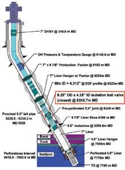
Well 34/11-A-9 T2 was drilled as a gas producer and during the final completion phase, it was not possible through pressure cycling to open the HP/HT isolation ball valve set in the 9 7/8-in. liner at 6,245.7 m (20,486 ft) MD/3,795.8 m (12,450 ft) TVD. After several failed attempts with wireline using mechanical override tools, it was decided to punch above it to allow well production passing the outside of the valve through the annulus between 9 7/8-in. liner and the 5½-in. tail pipe. However, the production performance was poor. A feasibility study evaluated ways to open or mill out the valve with the objective to improve the production characteristics and to allow access for future production logging.
The decision was to mill the stuck-closed isolation ball valve using coiled tubing (CT). Statoil had not performed any HP/HT CT operations and the available experience was limited.
To minimize uncertainty relating to depth determination during milling, a telemetry system ran at its operational pressure and temperature limits to provide real-time casing collar locator (CCL) readings in addition to downhole pressure and temperature data.
The Super 13% chrome, 110 Kpsi yield isolation ball valve was stuck closed at a deviation of 57.8º. Its ID when open is 4.25-in with a drift ID = 4.151 in. The EOF seating nipple at 6,223 m (20,411 ft) MD from the rig kelly bushing was ID = 4.31 in., which represents the minimum wellbore restriction from surface down to the ball valve depth.
The 34/11-A-9 T2 well is in the Statfjord formation with the top of perforations at 4,313 m (14,147 ft) TVD. The original prognosed reservoir pressure was 770 +45/-14 bar (11,168 + 653/-203 psi) and the downhole temperature at reservoir was 160º C. The shut-in wellhead pressure was 571 bar (8,282 psi) in March 2011. The expected downhole temperature at the ball valve was 145º C (293º F). The H2S and CO2 concentrations in the produced gas were less than 5 ppm and a concentration of 3.477 mol %, respectively.
A feasibility study including an onshore milling test evaluated the possibility of milling the isolation ball valve with an electrical mill assembly run on mono-conductor wireline cable. The report concluded with large uncertainty regarding the number of bailer runs necessary to remove debris above the valve and reach milling depth, as well as the lifetime for the electrical milling equipment at the very high downhole temperature. Based on this study and the low estimated likelihood of success (30 -- 40%), the Kvitebjoern license decided not to proceed with the wireline alternative.
New feasibility studies evaluated using CT, rig-assisted snubbing, and the rig for opening or milling out the isolation ball valve.

The CT alternative seemed to be feasible since similar jobs were performed at lower temperature and shallower depths, but the 15K psi well control equipment and CT string design would have to be specified and sourced specifically for the job.
The main drawbacks for the rig-assisted snubbing were the drilling crew's rig-assisted snubbing experience, rig-assisted snubbing personnel experience, ram-to-ram stripping experience, and HP/HT well conditions.
For the rig alternative, the main risks were gas migration to the surface in addition to more time and cost relating to killing the well.
It was decided that the primary method to be further evaluated and developed for removal of the ball valve restriction from the well would be CT, the secondary method would be rig-assisted snubbing and the final method would be to use the rig.
Concept selection
During the concept selection phase, the recommended method for deploying CT to remove the isolation ball valve from the wellbore consisted of the following steps:
Pre-CT job "pump and bleed" operation. Displacing the wellbore from the current gas by repeatedly bullheading 1.044 sg 40/60% MEG/fresh water from the kill wing valve of the christmas tree and bleeding the gas that migrates to surface. The aim of this "pump and bleed" step was to reduce the surface shut-in wellhead pressure (SIWHP) to the minimum before running the CT. This had advantages in safety and operations.
CT drift and cleanout run(s). The well was producing intermittently for few months through punched holes above the closed ball valve. It was suspected that fill and debris might have settled above the ball valve with the 11.5-m (38-ft) interval between the punched holes and top of the ball valve being particularly vulnerable. Offshore crane capacity limits and the long CT string needed to reach the ball valve at 6,245.7 m (20,492 ft) MD RKB, the maximum CT string size that could be shipped in one piece was 2- in. OD. The well completion from surface to approximately the ball valve depth was 7 in., 35 lb/ft tubing with a 6-in. ID. Therefore, it was impossible to generate enough turbulence in the annulus between the tubing and CT to lift any fill or debris when run in hole (RIH) with the milling bottomhole assembly (BHA) to mill the ball valve. It was decided to RIH first with a with venturi jet junk basket (VJJB) to drift and clean out the wellbore to the top of the ball valve.
CT milling run(s). This was the ultimate run to achieve the job objective and mill the ball valve. The motor needed to provide enough torque to mill through the ball valve. In addition, its operating pump rate should be achievable through the specially designed 2-in. CT string. A yard test and a successful milling job of a similar ball valve in a well operated by Shell in the British section of the North Sea were on record. The mill was a 4.1-in. OD dome profile ball mill run with a hydraulically (pump rate) operated shifting tool and an anti-stall tool. All lessons learned during this Shell job were taken into account for this Kvitebjoern CT project. The mill was designed and tested to mill through the ball valve material. The mill size for this Kvitebjoern job was decided to be 4-in. OD to deploy the milling BHA through the 41⁄16-in. 15K psi CT BOP. This mill size is big enough to allow later production logging tools to run through the milled hole. This critical detailed planning phase took approximately five months. It consisted of organizing several meetings and coordinating between different departments, disciplines, and third parties.
Offshore execution
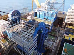
The job went as planned. The CT job was carried out through the drilling rig. The ball valve was successfully milled and drifted with the 4-in mill and the access to the lower wellbore was regained.
No serious HSE & Q incidents were reported during this first HP/HT CT job in Statoil and the Norwegian continental shelf with a high operating factor of 96.2%.
The total job duration was 31.6 days with equipment rig up including "pump and bleed" of 10.9 days; one VJJB clean up run and three milling runs totaling 9.1 days; extra production test and one extra drift run with VJJB through and below the milled ball valve, 6.1 days; and equipment rig down and back load, 5.5 days.
Operational risk analysis
An operational risk analysis log sheet and risk register covering the different steps of the operation was elaborated during detailed planning. This was important because this was the first HP/HT CT operation in Statoil and in the NCS.
The risk assessment involved representatives from all concerned disciplines within Statoil, including reservoir, well intervention, drilling and production, plus Statoil discipline advisors for CT, well intervention, well integrity, HP/HT, and well control, as well as third-parties representatives for CT services and the rig contractor.
The probability and the potential impact for each initial risk were assessed using a standard risk tolerance matrix. Prevention and mitigation actions were identified for each risk with the objective of reducing the probability and/or the potential impact of the corresponding risk.
This resulted in a detailed operational risk register including 41 identified hazards and 84 risk prevention and/or mitigation measures that were implemented during the planning and execution phases.
This risk register was sub-divided into 11 sections as following:
| 1. Mobilization and demobilization 2. Spotting and equipment rig up 3. "Pump and bleed" operation 4. VJJB drift and cleanout run(s) 5. Milling run(s) 6. Well control stack up 7. BHAs 8. Fluids 9. Contingency scenarios 10. Rig down equipment 11. Simultaneous contingency situations in A-9 T2 and a second well. |
Lessons learned
There were a number of lessons learned on this project. They key lessons are described below.
Telemetry tool performance. The telemetry tool provided valuable CCL data to correlate the depth down to the ball valve. The telemetry tool failed in three of four runs at a bottomhole temperature around 145ºC (293º F). However, the CCL logging signal failed after the initial depth correlation. The telemetry tool was running properly for its first few hours of exposure under extreme downhole pressure and temperature conditions before it failed. It was a known and accepted risk prior to operation that the tool might fail if exposed to downhole conditions close to or above its operational specifications of 8,000 psi/150º C (55 MPa/305º F) for a prolonged time. It could be concluded from the data that the telemetry tool operated properly up to 564 bar (8,180 psi) and 146º C (295º F) before failure.
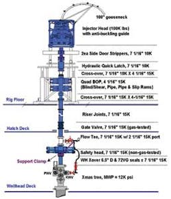
Equipment availability. The equipment availability for this special and non-frequent HP/HT CT job was a challenge. Early planning and ordering of some critical equipment was vital, especially knowing the day rate of the drilling derrick to be used. This critical equipment included both CT strings, the gas tested 71⁄16-in./15K psi gate valve, the safety head handler, the gas-tested christmas tree crossover, and the 21⁄16-in 15K psi gas tested gate valves. Weekly meetings to review critical items were held with the CT contractor. The need for long lead items was identified early in the project, and Statoil issued purchase orders for relevant equipment.
Site surveys. Three site surveys were carried out by Statoil and CT contractor representatives to avoid conflict with platform interfaces, and to identify any limitations or special requirements.
Personnel HP/HT training. Two full-day sessions of CT awareness and HP/HT seminars were organized and presented by the CT contractor to all involved personnel before the job start up.
Bleed off procedure. The bleed off needed to avoid explosive decompression of well control equipment elastomers was not provided by the CT contractor. Rather, the local platform best practice used during wireline operations was followed during this CT job. For future CT HP/HT operations, the bleed off procedure should be based on recommendations from the original equipment manufacturer for standard and high-pressure well conditions, respectively.
Pump and bleed operation. Liquid losses into formation were experienced during the "pump and bleed" phase and it was not possible to reduce the WHP. It was decided to abort the pump and bleed operation and to start running in the well while circulating through the CT. This alternative was effective in reducing the WHP.
CT weight simulations. A drag reduction by 25% (from 0.24 to 0.18) was observed when displacing the wellbore with metal-to-metal friction reducer while RIH from 4,200 m (13,776 ft) MD RKB to the ball valve. Data proves that the actual CT RIH and pick up weights were within the operating limit at 80% yield of CT string material.
Milling through the ball valve. It was difficult to control the weight on bit (WOB) at 6,245 m (20,484 ft) MD while pumping 40/60% MEG/fresh water at 400 l/m pump rate and at 340 to 375 bar (4,931 to 5,439 psi) CT circulation pressure. During the first milling run, the WOB was set down gradually but the motor stalled 15 times. The first milling BHA was pulled to surface for inspection. During the second milling run, milling was carried out with patience for longer periods without increasing the WOB. Vibration and an anti-stall tool was expected to provide sufficient WOB. The top part of the ball valve was milled during the second run in approximately 12 hours and the bottom part in an additional 12 hours. The experience gained from the first milling run was used to optimize the milling parameters of the second and third milling runs, and succeeded to break through the ball valve with the 4-in. mill at the end.
Confirmed milled ball valve. A 3D multi-finger caliper log was run on wireline two months after the CT milling job to investigate the wellbore status, particularly the milled ball valve area. The ball valve was confirmed to be milled out with a minimum ID of 3.97 in. at 6,245.7 m MD.
Conclusion
This CT project represents an excellent reference for future HP/HT CT operations for Statoil in Norway and worldwide. The job execution was performed as planned and in compliance with the relevant industry standards and local regulations. The stuck closed isolation ball valve was successfully milled and drifted with the 4-in. dome profile mill. No serious HSE&Q incidents were reported during this first HP/HT CT job in the Norwegian continental shelf, which had a high operating factor of 96.2%. Valuable lessons learned from the planning and execution phases of this challenging operation should be useful in future similar HP/HT CT applications.
Acknowledgements
The authors thank Statoil ASA, Baker Hughes (CT services with telemetry system), Hunting Welltonic (milling and downhole tools), Rolls Royce (safety head handler), and Tomax (anti-stall tool) for permissions to publish this paper. This article is excerpted from a presentation made at the SPE/ICoTA Coiled Tubing and Well Intervention Conference and Exhibition held in The Woodlands, Texas, March 27-28, 2012. (Ref. SPE paper 154433)