Asset integrity management extends reach

M.F. Renard
Bureau Veritas
The value of asset integrity management systems (AIMS) is reaching into more corners of offshore oil and gas exploration and development. It is not only used for FPSOs, but also TLPs, spars, and semisubmersibles. It is applicable to fixed platforms, too.
Bureau Veritas has fielded requests for AIMS support for equipment at the seabed, from flowlines and risers to vessel moorings, topsides, and offloading equipment.
Operators and service companies see two broad benefits in implementing AIMS. The first is the obvious need to keep track of what is happening with these high capex, long-term investments to maximize the returns.
The second broad benefit is to harmonize systems and procedures across multi-discipline teams spread across different parts of the world. While each AIMS can be specific to a facility, the consistency of the processes and tools used makes the results comparable and coherent. It improves information and documentation transfer.
The AIMS process also is flexible enough to be tailored to what an operator wants to know about a specific installation.
Combined, these can help minimize production shutdowns, and optimize maintenance and repair costs.
Offshore floating units are usually deployed under a long-term plan to handle the field production. This means they cannot be easily removed for dry-docking and repair. An AIMS has been developed for complex, major floating units and currently is in operation for several major oil companies.
AIMS is implemented to ensure management and continuous follow-up of all floating units regarding safety, environmental, operational, maintenance, and quality management. It includes recommendations on inspection, maintenance, and repairs. The main activities called for in this program are:
- Structural and mooring analysis
- Qualitative risk-based inspection (RBI) implementation
- Yearly review of the inspection, repair, and maintenance (IRM) plan
- Data management and storage
- Assistance for emergency first response.
Bureau Veritas' VeriSTAR AIMS is an open Web-based system with controlled access that allows AIMS teams to work worldwide. The system is designed to improve inspection management and information control for different types of facilities. Information is stored and secured in a unique database and can be accessed in real time through the Internet or an intranet.
Integrity management cycle process
The integrity management cycle process comprises four main tasks:
| 1. Development and maintenance of finite element models (FEM) and management tools 2. Periodic reassessment of unit condition 3. RBI analysis and IRM cycle 4. Establishment and maintenance of emergency response preparations. |
Modeling software, data management tools, calculations services, and other analysis/trends are provided within the scope of the First Assessment phase, which establishes the basis of the integrity management cycle process.
The IRM plan for a given facility is developed based on engineering analyses, RBI analysis, operational constraints, and inspection results. The plan is developed and optimized regularly from the unit's existing IRM plan. This system helps the inspectors and all concerned people to better control the integrity of structures, moorings, and offloading systems.
FEM and management tools
The available tools, including software solutions for structural FEM analysis, hydrodynamic and mooring analyses, inspections, and data management, are fitted to support every step in a unit's integrity management cycle process, from IRM activities through the annual review of the asset condition.
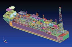
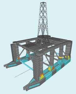
A global structural model is provided for each floating unit using finite elements modeling, depending on the shape of the floating unit (ship-shaped, barge, TLP, or spar) and on building materials. All items of the hull contributing to the resistance or to the stress of the structure are modeled.
Environmental data considered in the engineering analyses of FPSOs are based on the latest meteocean data for each specific site, including waves, current, and wind characteristics.
Load cases corresponding to the actual operating conditions used onboard are taken into consideration in order to assess the stress and fatigue induced in the structures by cargo, ballast, and other operating loads.
Fatigue life of selected details in the hull must be calculated. The calculations are based on production loads, local design, and local weather. The procedure to establish fatigue life uses the Miners summation approach, using stress-cycle (SN) curves.
Each floating unit is also provided with a mooring system database (mooring lines, dynamic positioning, offloading buoys, etc.). Hydrodynamic response of the floating unit is assessed to provide input data for the mooring and the structural FEM analyses.
For units coupled by flowlines, ropes, and gangways, for instance, a model containing the different floating units and their links is built.
Assessment of floating unit condition
The main objectives of the floating unit assessment condition are:
- Analyze inspection results and establish trends
- Compare monitored observations with finite element analysis
- Evaluate consequences of possible modifications
- Evaluate effects and consequences of structural degradation
- Evaluate longevity of structure
- Mooring and anchoring calculations.
Engineering analyses, such as hull and topsides structures, anchoring and liaisons, provide information about asset integrity. Annual reassessment reviews the structural integrity of the asset, analyzes the effects of modifications (environment, design, operations, etc.), and trends (steel wastage, corrosion, crack propagation, etc.), and validates the forecast of structure condition (fatigue, etc.).
Inspection results are reviewed yearly and recommendations on maintaining asset integrity are drafted for implementation. If relevant alterations have been made (thickness measurements, environmental data, monitoring data, cracks observations, etc.), models might be updated and the IRM plan optimized accordingly. Depending on the inspection results, some re-analyses may be run using the updated data in order to have a real condition reassessment of the floating unit and to show its evolution compared to the known history of the floating unit.
Once inspection results are available, depending on the findings, the following additional engineering analyses may be required:
- Structural reliability analysis
- Corrosion assessment
- Fracture mechanics assessments
- Fatigue analysis (structure and moorings)
- Structural code checks.
Qualitative RBI analysis is done to optimize the IRM plan to define and optimize inspection and maintenance intervals, develop and organize inspection plans, and propose maintenance and repair strategies.
Re-analysis is completed before the annual review of assets conditions.
Emergency response service
Emergency response service (ERS) is provided to assess damage stability and longitudinal strength of a floating unit. The following types of damage are considered in the ERS scope:
- Mooring line(s) failure
- Structural (and therefore stability) damage
- Mooring line(s) failure and structural damage.
Models can also support the decision-making process during an emergency and to help structural engineers and experts establish the best solution to protect or save the asset and the environment.
Documentation and data management
As an open Web-based system, controlled access to VeriSTAR AIMS allows worldwide team members access to support at each step of the integrity management cycle process. The system is designed to improve inspection management and information control for different types of facilities. Information is stored and secured and can be accessed in real time through the Internet. This information includes preformatted detailed reporting for asset integrity participants and simplified reporting for management on a unit and fleetwide basis.
A typical list of data included in the collection encompasses drawings of the hull, mooring system, and topsides structure. Engineering analysis data collections include reassessment results, FEA calculations results, and RBI results.
Inspection management tool
The main objective of the inspection management tool is to support the AIMS program along the Integrity Management Cycle process. The tool is based on a pre-defined unit's system tree, which is customized and described based on the asset configuration, and for the systems and equipment included within the AIMS. All information and IRM activities records are stored and linked to the respective system or item described in the asset's system tree. A graphical interface is used to quickly locate relevant information.
The classification and statutory status section of the software stores Class data such as floating unit references (name, location, flag, etc.), classification notations, certificates with expiration dates, and Class reports.
Structural FEM database
The structural FEM database provides all information about the condition of the facility. A 3D viewer allows users to examine the finite elements analysis and results, rule checking, and data management.
The model is used for different finite elements calculations to verify yielding, buckling, and fatigue strength of the structural components.
Each floating asset has its own dedicated database that can be developed at the start of design or at any time during the unit's life.
Typical contents of the finite element model database are:
- Global hull structure including FEA models and results
- Material properties
- Coating condition
- Corrosion condition
- Cathodic protection condition
- Thickness measurements
- Special specified details (turret, helideck, topsides, offloading platform, etc.)
- Relevant information on the hull and topsides assessment.
Finite element calculations and results can be examined. The user can verify the loads considered in the calculations and examine calculation results by manipulating the vessel's 3D views.
The database often begins in the as-built state, even if the facility enters the system during its service life. This state represents the start of a facility's history. All events entered into the database will be compared to this initial state. After each survey, the hull condition is analyzed and stored in the database. This makes steel renewal and repairs easy to forecast and optimize. Documented survey photos also can be stored in the database for a pictorial history of the unit.
Mooring system database
The mooring system database has been developed using ARIANE-3Dynamic, an integrated mooring and hydrodynamic analysis software for frequency/time domain mooring simulation analysis.
The database provides the AIMS team with information on the "as-installed" configuration of the facility mooring system. The purpose of the database is to have an updated model ready to perform the reassessment of the mooring system for emergency response.
Typical mooring system database contents are:
General data. Data regarding the floating support, external bodies (shuttle tankers, loading buoys and accommodation barges), bathymetry, and reference points required for performing any static and time domain analyses.
Mooring system. Data regarding the geometry of the mooring system and its composition required for static and time domain analyses.
Dynamic data. Added mass matrix, damping matrix, QTFs (used to calculate the second-order wave drift and mean wave drift loads) and RAOs (used to calculate the first-order wave motions) for calculation of the environmental loads on the system in the time domain.
Wave, wind, and current data. Type of wave spectrum, amplitude, period, and heading; type of wind spectrum, velocity, and heading; current speed and heading.