Innovative high-voltage switchgear key to subsea compression
Terence Hazel
Pierrick Andrea
Bethsabée Roger
Schneider Electric
The Ormen Lange pilot in Egersund, Norway, is the first subsea power distribution system to go into operation. Although still in a shallow water test phase, the concept of subsea power distribution is validated and will help prepare the industry for future subsea processing facilities that require large amounts of power.
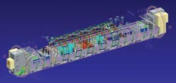
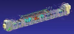
The subsea circuit breaker module (CBM) is a long cigar-shaped enclosure. The following explains what is inside and why.
Power equipment
The pilot subsea gas compressor motor is rated 12.5 MW and is used together with a 400 kW pump. The long tieback makes subsea power distribution necessary. The equipment in the CBM is 36 kV class and the subsea system voltage is 22 kV. Auxiliary power is provided via a transformer and is backed up by an uninterruptible power supply (UPS) in a separate subsea module.
Circuit breakers and protection devices that could operate within an oil-filled, pressure-compensated environment are not yet commercially available. The switchgear is in an enclosure that provides a 1-atm pressure environment. Dry nitrogen fills the enclosure. Its physical properties are close enough to air to allow standard electrical equipment to be used.
The high-voltage (HV) circuit breakers are proven 36 kV class air-insulated devices. These circuit breakers are also used in arc furnace applications which are characterized by their severe switching duties.
The other HV devices used are proven 36 kV class magnetic core current and voltage transformers. Since there is no human access to the HV equipment, the subsea enclosure is equivalent to a terrestrial switchgear lineup and thus the devices are installed in an open-air substation fashion as described below. The busbars are bare copper.
The low-voltage (LV) switchgear consists of proven motor-operated circuit breakers, protection relays, contactors, and fuses. These have been used in marine applications for many years and have a very good resistance to shocks and vibrations and very low failure rates. The selected voltage class of the equipment ensures correct switching in the dry nitrogen atmosphere. The LV switchgear is installed in a metallic cubicle to reduce electromagnetic interference from the HV switching devices. If the LV switchgear was in a separate subsea enclosure, rack mounting could be used.
Fuses were used for many of the auxiliary circuits which consume little power and are not subject to overload conditions. The only electrical failure modes are short circuits or earth faults. A circuit with a short must be quickly isolated to prevent fault propagation or nuisance operations in healthy circuits. Such faults cannot be repaired subsea so there is no question of trying to reenergize such a circuit. Fuses are adequate for this and do not have the failure mode of opening due to a mechanical shock. All LV circuits which could be overloaded are protected by devices which can be remotely reset and reclosed.
Subsea switchgear electrical system design
A system is more than the sum of its parts. System aspects play a large role in the selection of the individual devices in order to be sure that they are fit for purpose for all operating conditions. To appreciate some of the system design considerations, it is important to understand the installation constraints within the CBM.
The majority of connections between equipment will be made via the LV switchgear cubicles. The requirement for progressive installation of the electrical equipment within the enclosure means the LV cubicles are the last to be installed in order to allow all connections to be made. This explains their location at both extremities. In order to limit the length of the HV busbar and its support system, it was decided to place all HV equipment together. The transformers are installed on both sides between the LV cubicles and HV circuit breakers. The result is a symmetrical installation.
The connections to equipment located outside of the CBM are through penetrators in the upper portion of the enclosure. The HV penetrators are above the connection points on the HV switchgear, and the LV penetrators close to the LV cubicles. The LV cubicles have horizontal rods that provide a specific landing area for all LV connections entering the enclosure. These rods ensure that no unacceptable stresses are applied to these connections.
Electromagnetic compatibility
There are many interconnections between both LV cubicles for redundancy of the auxiliary power supplies. Since the LV cubicles are installed at both ends, these LV power, control, and measurement interface cables transit the enclosure. All HV power cables as well as the main LV power cables also are located here. To ensure electromagnetic compatibility (EMC), the cable routing throughout the enclosure is designed to maximize the distance between the HV power cables and the control and measurement cables. The HV power cables are installed at the bottom of the enclosure, the LV power cables toward the lower sides, and the auxiliary power supply, control and measurement cables in cable trays along the upper sides.
Proximity of HV circuits requires a specially designed earthing system to avoid coupling resulting in transmission of electromagnetic disturbances to the control and measurement circuits. The conceptual earthing study defined measures required to reduce coupling. The earthing system was executed based on these principles.
The choice of the steel used for support structures is important for EMC. Carbon steel is much better than stainless steel. Since there is no oxygen in the enclosure, carbon steel will not corrode. Stainless can be used but additional shielding and earthing may be required to achieve the same EMC performance.
Auxiliary power supplies
Auxiliary power supplies are the Achilles' heel of power systems. Availability can be enhanced through redundancy. This is tricky because redundancy often means more equipment, bringing additional failure modes. The LV power distribution system is designed for fault tolerance under normal operating conditions and during the planned maintenance of the UPS, during which time it will be disconnected. Fault tolerance similar to Tier 3 in data centers is achieved for operation with either one or both UPS in service. Redundant protection is also provided for the HV circuits.
Protection system
The analysis of the protection system started with a complete redefinition of the performance requirements. Typical terrestrial protection schemes are not adequate for subsea systems due to inaccessibility for maintenance. The basic functions of the protection system are designed to quickly eliminate equipment that has an electrical fault, and to prevent overload conditions from damaging sensitive equipment such as connectors. An overload condition is not an electrical fault but will trip a circuit breaker. Since the same protection relay will trip the circuit breaker for both electrical faults and overload conditions, the operator must accurately identify what caused the circuit breaker to open. If due to an overload condition, the circuit can be reenergized after elimination of the overload. If it is due to an electrical fault, the circuit must remain deenergized. Since it is not necessary to implement specific functions to protect persons, the protection system can be optimized for selective fault clearance and identification of overload conditions.
Interface engineering
The confined space and the specific nature of some components of subsea installations make interface engineering even more challenging than for terrestrial installations. This is true for the mechanical interfaces to the enclosure for both equipment installation and electrical connections.
Thermal engineering
Thermal engineers confirmed that the heat generated in the enclosure under all operating conditions would be correctly dissipated through the enclosure wall to the surrounding water using natural convection only. Forced cooling was not an option due to the additional failure modes it presents. Thermal simulations were conducted for all loading conditions and for the test pit installation with a water temperature of 13°C (55.4°F), and the final installation on the seabed with a water temperature of 4°C (39.2°F).
Different operating modes produce different losses. The most severe combination of losses was used to check that no operating conditions resulted in unsatisfactory hot spots, including locations within the LV enclosures.
The choice of horizontal installation facilitated the thermal engineering. The trend in the subsea market today is for vertical installation to reduce the template footprint and for ease of handling of the payload while making the best use of standard installation vessels. Changing to a vertical installation is not as easy as it may seem. For example, transformers being heavy will be installed at the bottom. However, the transformer losses will heat all equipment installed above them. Installation of heavier equipment at the bottom also prevents symmetrical installation of the identical sections of equipment. While vertical installation has its benefits, the design must be carefully engineered.
Mechanical design
Mechanical engineering ensured that the CBM would withstand the constraints during all project phases. Operating constraints considered were mechanical shocks when operating the HV circuit breakers and transformer vibrations. Environmental constraints were 15° pitch and 30° roll during transportation and handling and installation on the seabed.
To provide the best mechanical interface, it was decided that fastening of the switchgear to the enclosure would only be at two points at the bottom. This allows maximum flexibility in the design of the switchgear without influencing the design of the enclosure.
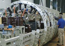
The mechanical design also meets the 1.5 g Dynamic Amplification Factor requirement and accounts for the mechanical effects of the highest possible short-circuit current. Other studies took into account the rated current and rated short-time withstand current, and the impulse rating of the switchgear. One of the results of these mechanical calculations was the busbar circular support system design.
Fabrication engineering
The main design challenge in equipment fabrication was how to install the switchgear in the enclosure.
The solution was to make a rack for each switchgear functional unit: voltage measurement, HV circuit breaker, transformer, and LV cubicles. This makes it possible to ensure the integrity of the switchgear after the factory acceptance testing (FAT), transportation, and final installation in the enclosure. Mechanical calculations were done for each rack to ensure that the racks and the enclosure would never touch during handling and installation.
The use of racks allows step-by-step installation, connection, and testing of the electrical equipment within the enclosure. Each switchgear rack has retractable wheels that roll on rails at the bottom of the enclosure. Each rack can be installed without any mechanical stress, and the wheels retract after the rack is in place.
All power connections between the racks are with flexible connections, and a specifically designed copper braid was used for the HV penetrator connections to prevent the transmission of any shocks or vibrations to the penetrator.
The racks were completely wired and tested prior to assembly for the FAT. All control and measurement and small power connections were made using bayonet-type connectors to prevent wiring mistakes during final assembly and loosening during installation. The racks in the center of the enclosure are installed first; the final racks are the LV cubicles.
Availability studies
The main design criterion for the subsea power distribution is the availability of power to the loads. Not only is it very important to select devices that are best suited for the subsea power system application, it is also necessary to use equipment that has a proven track record and thus a well-known failure rate, λ. The λs of all devices making up the electrical distribution system are used in the overall availability study.
The availability study began at the very start of the project along with the first engineering task. All decisions made during the electrical, thermal, mechanical, EMC, fabrication, and installation designs were reviewed to determine if they had a positive or negative influence on the availability of power to the process loads. All the design aspects were integrated into the availability study in a continuous iterative process.
where MTTF is the Mean Time to Fail and MTTR the Mean Time To Repair. Due to the difficulties retrieving subsea switchgear and the resulting process outage, it was necessary to make the MTTF as large as possible since little could be done to reduce the MTTR.
Maintenance requires retrieval of the complete subsea power distribution module (which is both time-consuming and expensive), so the MTTR is high by essence. Partial maintenance is not possible because all components are fitted into one CBM. There is always a trade-off when considering modularity. Smaller modules, such as one independent module for protection and control, make equipment recovery easier and reduce MTTR. This results in an increase in the availability. Smaller modules, however, involve more penetrators and connectors which adds additional failure modes. Along the same lines, redundancy increases the availability by increasing the MTTF but involves more components and more connections. Availability studies are key to providing the data required by engineers to make the correct decisions. After careful consideration, redundancy was used for auxiliary power systems, protection, control, and communications. Moreover, the auxiliary power was made redundant without regard to the number of UPS modules actually in service.
A "leave nothing to chance" principle was adopted for the qualification of all equipment, devices, and components, from the design stage to final testing. All components used were identified and thoroughly documented during the selection process, including the reasons for selection or for rejection of similar components. Correct operation of all components, equipment, and systems was extensively verified according to test procedures developed for all phases of integration in the CBM including manufacturing, assembly, and FAT. The performance of the CBM was demonstrated through extensive engineering.
The availability study was carried out for the CBM as an independent system that was part of the complete power distribution system. The results of the CBM availability study were provided to those responsible for the overall system design for the complete plant, from the shore station to the process loads.
Conclusions
The subsea HV power distribution system was designed, manufactured, assembled, and tested to meet the design constraints posed by equipment being installed on the seabed without human access for maintenance and operation. Documenting the rationale for the selection of each individual component used, no matter how small, is critical to achieve high availability of the power system. Extensive thermal, mechanical, electrical, EMC, and fabrication engineering is essential to verify that the equipment complies with each and every stage of the overall project including assembly, transportation and handling, testing, final installation, commissioning, and commercial operation.
When designing systems, the normal operation as well as all possible modes of degraded operations must be taken into account. The acceptable limits for each possible degrade mode must be defined. The selection and integration of components into equipment and systems must allow for thorough testing at each step of assembly. This is a key challenge when designing the equipment racks.
After the pilot project was completed, several studies were done to assess the system's strengths and weaknesses. This resulted in several suggestions for improvement of the subsea electrical power distribution system as a whole. This maturity study optimized the HV AIS architecture and paved the way for the use of HV gas insulated switchgear (GIS) for subsea power distribution and control. The electrical and mechanical interfaces were also addressed to better adapt the designs of the electrical equipment in future projects. A new concept for a dedicated monitoring and control system was created to enhance the overall availability of the switchgear.
The technology advances related to the Ormen Lange pilot project are very useful in the design and execution of the Åsgard LV power distribution module. Recent publications show how these concepts can be integrated to provide a complete subsea HV-LV substation equivalent to terrestrial systems.
Today's subsea applications are based on radial distribution systems. In the years to come, subsea applications are likely to use additional architectures such as loops in order to allow the adaptation over time of the power distribution system to match the development of the subsea reservoirs.
Offshore Articles Archives
View Oil and Gas Articles on PennEnergy.com


