Mike Moffat
Chris Lynch
Corrpro Companies
Several offshore installations originally designed for 20 to 30 years in the North Sea have now been in service for over 40 years. The number of aging offshore structures and pipelines grows each year as more operators look to extend their life due to the development of new practices and technologies. Complex engineering solutions are required to ensure continued asset integrity. This requirement was initiated and is supported in the United Kingdom by the Health and Safety Executive under Key Programme 4 (KP4) Aging and Life Extension (November 2012).
Most structures or pipelines were originally protected using sacrificial anodes, and many of these systems are now either approaching depletion or beyond their original design efficacy.

While most certifying authorities and standards organisations provide CP guidance and recommendations for the design of systems for new offshore structures and subsea pipelines, there is currently little or no data available for designing and implementing CP upgrades to existing assets.
There is a growing demand to design CP systems that can be retrofitted to enhance an existing system, in order to continue corrosion mitigation throughout the extended life of the structure or pipeline.
Collating historical data of the original CP design, including operation and maintenance records, is essential. In some instances, a permanent CP monitoring system comprising a number of reference electrodes and monitored anodes that provide real-time data may have been installed. However, because these systems are not mandatory, they are in the minority. Without a permanent monitoring system, it is necessary to carry out regular CP surveys during routine structure inspections, typically using an ROV.
Traditionally, ROV operators record structure-to-electrolyte potential data at stab points that are rarely repeated from one survey to the next. Unless care is taken to establish and repeat the point at which the measurement is taken, it is difficult to make any prediction on future performance of the CP system.
Frequently, ROV operators report visually on the condition of anodes and remaining alloy in terms of percentage wastage, such as 15%, 50%, 75%, etc. This provides only an estimation of anode consumption and is sometimes made even without knowledge of the original anode dimensions; or without having first cleaned the anode to remove any marine growth or bi-products from the surface. Cleaning of the anode is essential to obtain an accurate assessment of wastage unless the anode is totally consumed and only the steel insert is visible.
By careful analysis of available CP data and review of ROV inspection measurements, trends in structure potentials and accurate anode consumption rates can be evaluated to establish when it is necessary to implement a CP upgrade. Ideally, this should be undertaken before this data indicates the structure or pipeline is no longer fully protected.
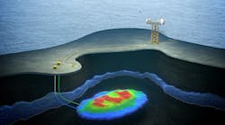
The associated graph shows recorded structure potential measurements at predetermined locations at -4.5m horizontal elevation. The graph indicates a dimensioning trend in protection levels and initiating, together with the evaluation of other detailed survey data, the requirement for a CP upgrade design and installation of a retrofit CP system.
Cathodic protection systems are designed to provide sufficient electrical current to establish protection at installation; maintain protection for the duration of the design life; and retain the ability to re‐establish protection even at "the end‐of‐life."
The amount of electrical current required to achieve this objective on a carbon steel surface in seawater varies with the rate of availability of oxygen at the surface. This is determined by factors such as water depth, flow rate, and resistivity. The latter is controlled by salinity and temperature. It is also known that if a structure has been polarized for a long time, calcareous deposits form on exposed steel surfaces and act in a similar manner to protective coatings by reducing the oxygen availability at the steel surface, thereby reducing the amount of current to maintain polarization.
Environmental conditions vary depending upon the offshore location. It is possible to select criteria for CP design parameters but this must be carefully assessed depending upon the structure location. Of course, condition in various locations can vary considerably, and result in a degree of excess anode material - or worse, not enough.
The retrofit CP design typically considers only the platform structure, including pile guides, piles and, where applicable, any conductors or other appurtenances. Allowances for other appurtenances such as risers, flowlines and other subsea structures should also be considered if electrical continuity exists with the platform structure.
The retrofit CP design uses conventional and modified CP criteria to maintain external structure potentials within the range of ‐800 mV to ‐1,100 mV with respect to silver/silver chloride (seawater) reference electrode, throughout the remaining service life of the platform, in accordance with international standards.
An important consideration in any CP design is coatings. Generally all platforms will have a coating system extended to the bottom of the splash zone. The remaining metallic submerged or buried areas of the platform below the seabed may also be coated, or they may be bare steel. The latter being the approach adopted by the majority of owner/operators forty years ago.
If a coating system was originally applied to all submerged areas, then it will be necessary to know the type of coating applied and the application procedure and final coating thickness (DFT). With time, natural degradation of the coating system will occur as well as areas that have suffered mechanical damage or where the coating has been damaged. This may also include areas where marine growth has been removed or where the coating has been intentionally removed for inspection purposes. It is therefore important to have an accurate assessment of the current coating condition when trying to establish what coating breakdown factor should be applied to the retrofit CP design. The DNV RP B401 (2011) Recommended Practice Cathodic Protection Design document provides guidance using formulas and factors for different types and thickness of coating systems, which can be used to calculate breakdown factors over the life of the structure. Although these can be used as the basis of a retrofit design, they tend to be conservative when trying to optimize the design. If reliable inspection data about the condition of the coating system can be obtained, a significant reduction in retrofit materials can be made.
DNV RP B401 (2011) recommends the following current densities should be used when designing offshore CP systems:

The above current densities are recommended for new uncoated steel structures or for steel surfaces exposed in temperate waters (7-11ºC) with a depth of 30 metres or less. In practice, the above criteria is known to be conservative for retrofit designs when structures remain partially or fully protected. Applying these figures would require a large amount of current being required and therefore an excessive number of anodes. Critically, DNV and other International Standard organizations recognize that design parameters may be varied based on local conditions and experience gained in operation.
If the structure is already protected, or partially protected, by an existing CP system, the higher level of initial current density recommended by DNV is not required for retrofit CP designs.
Corrpro has carried out assessments on several North Sea structures. Review of historical structure CP survey data has consistently shown maintenance current densities of between 10 and 30 mA/m² on polarized structures. These figures are similar to other measurements recorded on southern North Sea structures, and reported by a major oil company after one of their platforms had been removed in 1979 after 15 years of service. The average current density reported was 25mA/m² over this period for the platform, which was uncoated below the low waterline.
A similar exercise was conducted by the same oil company on another coated structure, and an average current density of 15 mA/m² over 16 years of operation was obtained. These figures were based on total anode alloy weight loss over the period, alloy capacity and both wetted and buried surface areas of the structure. Based on this and other previously documented data of southern sector North Sea structures, the use of reduced criteria is justifiable.
Corrpro has used the following current densities for retrofit CP designs for structures in the southern sector of the North Sea. The structure has been divided into zones in order to calculate the total amount of current required to maintain polarization:

In Zone 1, where the structure is affected by wave action, higher current densities have been applied. In Zone 3A, the recommended DNV criteria has been used for buried areas. For deeper buried areas (two meters and below), the current density has been reduced to 10 mA/m², as it is generally accepted that the concentration of oxygen reduces considerably below this depth. A reduced current drainage allowance to well casings by a similar factor from the DNV value of 5 A/well to 2.5 A/well has also been used.
While the above current densities contain some contingency over actual reported values, they do represent a significant reduction in the DNV recommended criteria. It should be noted however that these figures relate to structures in the southern sector of the North Sea. They should not be adopted for other locations without first having completed an extensive review of historical CP data and local environmental conditions.
Once the retrofit CP design criterion has been established, anode quantities and sizes are calculated to ensure sufficient current to maintain polarization; or to ensure that full protection of the structure can be maintained. If the retrofit design uses sacrificial anodes, then the total net mass of anode material is also calculated (based on mean current density requirements), to ensure that enough anode alloy remains at the end of the extended period.
Once current requirements have been calculated to achieve the criterion, a choice has to be made between using a sacrificial anode system or an impressed current and/or a combination of both, referred to as a hybrid system. The technical advantages and disadvantages of these systems will need to be assessed. This will be based on experience gained with previous retrofit designs and installations that have demonstrated a proven track record for effectiveness, performance, reliability, ease of operation and installation, plus provide the most cost effective solution. Structural and environmental factors should also be taken into consideration. For some structures, this can be a very complex process, requiring much iteration before arriving at a suitable design and installation.
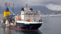
The requirement to minimize offshore installation time is driven by the high cost of marine vessels that have the necessary equipment and personnel to facilitate the retrofit installation. This cost can be up to hundreds of thousands of dollars per day for a large dynamic positioning (DP) vessel with full support services. The retrofit CP system should therefore be designed, when possible, so that installation can be made using an ROV to minimize or even eliminate intervention by divers.
Some factors to be considered when selecting the type of CP system used for retrofit installations include:
- Provision of CP system commensurate with owner/operators stipulated extended life of the structure
- Minimize offshore installation time
- Use only an ROV where possible
- Evaluate complexity and density of subsea assets and debris
- Evaluate electrical isolation of platforms from pipelines or other foreign subsea structures
- Minimize interference to other metallic subsea structures
- Provide sufficient operational flexibility to accommodate expected changes in the environment, the coating (if applicable) and the operation of the structure during the system service life
- Adhere to all applicable codes and standards as well as health, safety and environmental requirements
- Use tried and tested technology to ensure long-term integrity and reliability
- The onsite availability of skills required to operate / maintain an ICCP system, if selected
- Implement a regular testing and monitoring program to ensure performance of the CP system can be tested and monitored with respect to industry standards and regulations.
The effectiveness and longevity of retrofit CP systems depends on totally electrically isolating the structure to be protected from any other metallic structures. If electrical continuity does exist then interaction might occur which could adversely affect the performance of the retrofit CP system. This has to be fully evaluated at the design stage to ensure the isolation between pipeline risers and other subsea structures is effective. If electrical isolation cannot be assured, then allowance for current drain to interconnecting assets should be included in the design if the existing systems are not fully compatible.
To maintain full protection or polarization, a CP current must be applied continuously throughout the extended life of the structure. Sacrificial anode systems are simple in operation and once installed only require a low resistance electrical connection be maintained between the anode and the structure and that both the anode and structure (cathode) are continually immersed in seawater.
Sacrificial systems are inherently self‐regulating whereas impressed current systems require the protection current to be controlled. To achieve control it is necessary to measure the level of CP at regular intervals using a permanent monitoring system or an ROV survey.
Impressed current cathodic protection (ICCP) systems are more complex and problems in maintaining such systems are well documented, especially in harsh offshore environments. Failures with water penetrating anode cable connections or damage to anode feeder cables do occur. Electrical power must be continuously applied to variable output transformer rectifiers. These units, although highly reliable, require regular and routine maintenance and monitoring.
The seabed around a platform can be complex, with numerous pipelines, flowlines and structures. In many instances, a substantial amount of debris can precipitate at the base of the platform. Problems associated with remote impressed current (IC) anodes located on the seabed are possible as a result of interaction/interference with other metallic subsea structures that are in close proximity. These scenarios need to be carefully evaluated to mitigate the possibility of stray current effects that can cause rapid metal loss on affected assets.
Sometimes onsite availability of skills required to operate and maintain an ICCP system can be an issue. The system should be operated and maintained by competent personnel after an ICCP system has been commissioned by the specialist CP supplier. A NACE CP specialist or an I‐Corr Level 3 senior CP engineer in marine metallic structures should only be approved by the owner/operator corrosion control specialist.
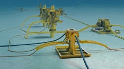
Cathodic protection anodes, whether sacrificial or impressed current, may be structure (locally) mounted or located on the seabed at a distance remote from the platform. In the event that mounted sacrificial anodes are used, it is normal for the mounting assembly to provide the prerequisite electrical continuity with the structure. In the event that sacrificial anodes are located on the seabed, an electrical bond from the anode to the structure is required. This can be achieved at seabed level by the use of a proven ROV installable continuity clamp located onto the lowest horizontal structure member. Multiple or single anode sleds can be deployed as a single lift and seabed placement with associated duplicate electrical connections. In this manner, both the offshore and ROV subsea work scope is minimized.

In the event that ICCP structure (locally) mounted anodes are used, the anodes need to be electrically isolated in a manner that provides a significant anode-to-cathode separation often using high integrity dielectric shields. The anode needs to be provided with external electrical power via a cable routed to the power supply mounted topside on the platform. As a result of the need to achieve adequate anode to cathode separation, IC anodes are often located on the seabed at a predetermined distance from the structure. These units still require an electrical connection cable routed from the seabed anode location back to the structure and to the topside located power supply. In the event that a vacant "J" tube or alternative casing is available, this may be used for cable protection. In the absence of such a facility, it would be necessary to provide cable protection and support throughout the water column. This will require complex ROV activity or diver intervention.
The most common form of retrofit CP system adopted in the North Sea has been by sacrificial anodes. These can be located on steel frames, typically called "sleds," and positioned on the seabed around the base of the structure or, alternatively, mounted on steel hoops in the form of a bracelet that can be clamped around a structural member. For anode bracelets, hardened concaved set-bolts located in each half of the steel hoops are used to achieve electrical continuity. Earlier retrofit systems in the North Sea used anode bracelets that have proven to be very reliable and provide good current distribution. The downside of this is the necessity to use divers, making installation very expensive. In later years, the sled design has become more acceptable as it is more cost effective.

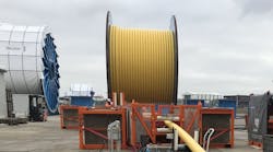
It should be noted during the design phase that if multiple anodes are fitted to a single sled, this will result in a reduction of individual anode current due to interference effect of the anodes being in close proximity to each other. Two bonding cables are pre‐connected to the sled and to continuity clamps that are attached to the asset. The use of two continuity cables provides redundancy should one cable become detached or suffer mechanical damage. These flexible copper cables need to be insulated and armoured for mechanical protection and be suitable for long-term use in seawater. The copper conductor needs to be of a suitable size to limit the voltage drop within acceptable limits, otherwise the output of the anode sled assembly will be compromised.