Deepwater steel catenary risers require attention to fatigue factors
Marin Abelanet
Daniel Karunakaran
Richard Jones
Stephan Eyssautier
Patrick White
Subsea 7
Steel catenary risers (SCR) are an attractive technology for deepwater field developments. SCRs are simple in design with few complicated components. They require high fatigue performance, especially at the top end and at sag bend. Increasingly, risers are wet stored on the seabed before the floating facility is moored. When SCRs are installed in deeper waters, their top tensions increase beyond the capabilities of many existing vessels. This makes the installation of SCRs in deepwater challenging.
The engineering, procurement, construction, and installation contractor can improve the fatigue performance of SCRs by proposing the best riser configuration and installation method; by reducing the motion that the SCR has to withstand during life of field; and by minimizing fatigue damage during installation.
Welding technology improvement can increase the weld quality, particularly important for sour service, where the welding of corrosion-resistant alloys increases the difficulty of the task.
Fatigue design
SCRs usually require a fatigue life of 10 times their service life, which generally equals a total of 250 years. This results in a very large number of cycles and, even in mild environments, the accumulated fatigue damage is usually the main driver in dimensioning SCRs.
The main causes of fatigue damage to risers are shutdown and re-start, vortex-induced vibration (VIV), waves and associated riser excitation due to floating facilities motions, and installation.
The operator decides the shutdown and re-start scenario; the contractor usually has no influence on this factor.
VIV is a much better understood phenomenon now. Slender bodies interact with an external fluid flow to produce periodic flow irregularities that result in vibrations. If the vibration period is close to the natural period of the system, it can lead to high amplitudes of movement and thus high fatigue. Since sea current is usually strong in deepwater, VIV is relevant to deepwater SCRs.
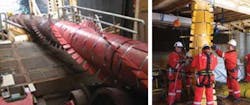
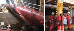
The most common solution is to add helicoidal strakes to suppress the cause of these vibrations. Installation does not present major issues; they usually come in lightweight half-shells, which do require additional time to be mounted offshore under the lay spread. In the case of S-lay, VIV strakes must pass through stinger rollers, and so need to be resistant to crush load and able to return to shape after exiting the stinger.
Waves and associated riser excitation due to floating facility motions are the main source of fatigue damage. It obviously depends on metocean conditions and the response amplitude operators (RAOs) of the floating facility. Both are given to the EPIC contractor to propose the best riser configuration.
Selecting the best SCR configuration
The first SCR was installed in the Gulf of Mexico in 1994 on a TLP at Shell's Auger project. Characteristics of a TLP include minimal excursion and heave, even under harsh conditions and the capacity to support high loads. The SCRs were promoted as a less expensive alternative to flexible pipe.
SCRs are usually free-hanging. They consist of a rigid pipe that may differ in thickness and/or grade from a static rigid flowline, directly welded onto it (at the "transition point") a few hundred meters from the touchdown point (TDP) or via an anchored subsea structure. At the top, a flex joint or a stress joint interfaces with the hang-off receptacle on the hull of the floating facility.
SCRs are all the more sensitive to dynamics when they are light in water. This can be caused by risers with thick insulation coating, gas production or injection risers, or risers combining both of these.
Risers with these properties are less resistant to fatigue.
However, some new configurations are emerging to tackle the issue of excessive fatigue damage at the TDP and at the top end. Buoyancies have been added midwater along SCRs to form a "lazy wave" design that aims to reduce heave transmitted from the floating facility to the SCR at the TDP. It also reduces the load at the top. Best results come when a minimum number of buoyancy modules are located close to the TDP.
The weight-distributed SCR is a concept for harsher environments. In this concept, qualified ballast elements are attached at certain sections of the SCR to reduce the stresses around the touchdown point and to enhance fatigue performance.
Both weight-distributed and lazy-wave SCRs are proven ways to reduce the stress at the TDP. Compared to a free-hanging SCR, such configurations can increase fatigue life by a factor of two to five times. Steel lazy wave risers (SLWRs) were first installed by Subsea 7 at Shell's BC-10 project in Brazil, in 2009.
Another new concept is the buoyancy supported riser (BSR) being developed for Petrobras' Guara-Lula in ultra-deepwater presalt Brazil. This system decouples motions of the floating facility by anchoring a large structure subsea to support the catenary load of the SCRs. It is essentially a hybrid system where flexible pipes join the buoyancy-supported riser to the floating facility. The BSR concept is best suited to ultra-deepwater developments. Subsea 7 is set to complete the design and installation of the first BSR by 2013-14.
During installation, the fatigue accumulated on a given SCR can vary depending on the vessel used. There is no standard, but a usual value for fatigue budget during installation is 5% of the total fatigue acceptable damage.
The fatigue damage during installation is influenced by the following factors:
- 1. Strain due to bending along the lay spread -- Reel lay imposes significant bending in the pipe (plastic domain), and S-lay also applies large bending moment combined with high tension, so much that supporting by stinger is required. J-lay is best in this respect as the hog bend is eliminated from the pipe path.
- 2. Exposure time to vessel motion during lay -- Reel lay is the quickest. Stick-lay (in J-shape or S-shape) is slower as welding non-destructive examination (NDE) and field joint coating are performed in critical time. Lay time may be reduced when double-jointing or quad-jointing onshore (prefabricating strings of two or four pipe joints together onshore or in hidden time onboard).
- 3. Motion at the lay spread location -- Vessel heave is critical to all methods, as it induces compression and bending at the TDP; larger vessels are more stable. If the lay spread is close to the center of the ship, the amplitude of pitch and roll is reduced, so the J-lay tower performs better when positioned midship; a moonpool is an advantage. If the vessel can weathervane while laying, its motions are drastically reduced. This is possible in J-lay, if the tower can tilt, but not in S-lay.
Once these main causes of fatigue are minimized, fatigue resistance depends intimately on the performance of the weld. The EPIC contractor can contribute by proposing high-quality welding.
SCR welding
The main challenge in any SCR design remains the fatigue performance of the weld. SCRs in deepwater can be subject to severe environmental loading, and the fatigue performance is often limited by the girth weld.
The prerequisites for fabrication of SCR welds include:
- Close control of pipe end tolerances and joint misalignment. Typical SCRs may require joint high/low to be controlled to a maximum tolerance of ±0.5 mm. Achieving this limit may require counter-boring the pipe ends, together with pipe end sorting and ID grouping.
- High-integrity welding. Close control of welding parameters is required to ensure freedom from lack of fusion defects and to provide satisfactory internal root and external cap profiles. Typical SCR specifications place stringent requirements on allowable welding defects.
- For high fatigue performance, it may be necessary to flush-grind the weld caps. This can significantly improve fatigue life in riser pipelines, where fatigue is limited by crack initiation at the cap weld toe.
Installation of carbon steel SCRs by reel lay is cost effective. A benefit for SCR fabrication is that the majority of the girth welds can be fabricated and inspected onshore in a controlled environment to ensure high weld integrity.
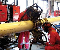
Subsea 7 has installed two reeled carbon steel riser projects: Blind Faith, in the US Gulf of Mexico, and BC10. The former comprised two SCRs with dimensions of 7.625 in. x 25.4 mm and 7.625 in. x 25.6 mm in API 5L x 60, with a total length of 2.6 km (1.6 mi). The latter comprised seven risers, with a total length of 21 km (13 mi) of 6-in. x 15.9-mm and 12-in. x 19.1-mm pipe in API 5L x 60. For both projects, mechanized hot wire pulse gas tungsten arc welding (PGTAW) was used for the mainline girth welds. This process gave good assurance of weld integrity together with excellent mechanical properties.
Clad pipe for reeled lay
The company has since developed a welding solution for reelable clad pipe. Until recently, reel-lay installation of clad pipe has been impeded by the lack of fatigue performance data. The objective of this program was to develop and qualify a welding procedure for clad pipe suitable for SCR service and to demonstrate that the required fatigue life could be achieved in the reeled condition. A weld solution was developed based on mechanized hot wire PGTAW using Alloy 625 filler wire.
A clad pipe weld procedure was qualified in accordance with DNV OS F101 - 2007 and typical industry SCR specifications. Automatic ultrasonic testing (AUT) was selected as the primary NDE method. Validation of the AUT inspection procedure ensured that planar flaws of concern could be reliably detected and sized. Clad pipe strings compromising representative butt welds were then manufactured and inspected.
These were subjected to a full-scale simulated reeling. The butt welds were then subject to full-scale fatigue testing by high frequency resonance. The fatigue performance exceeded expectations, with most test samples failing in the parent material with fatigue levels close to the Class B mean curve.
Although the mechanized PGTAW can produce high-integrity girth welds, welding productivity is limited. For this reason, mechanized gas metal arc welding (GMAW) was developed to achieve higher production rates while maintaining acceptable weld quality.
A critical feature of this welding method is the use of the CMT (cold metal transfer) for root welding. This is an advanced GMAW technique that allows the weld root to be deposited precisely with minimum heat input, giving good control of the weld root quality and profile.
Subsequent weld passes with the PGMAW process give good weld fusion characteristics and mechanical properties. This welding solution has been developed and qualified for both carbon steel and clad/lined pipe.
A key to reel-lay installation of mechanically lined pipe is to avoid wrinkling damage to the liner. This is done using internal pressurization. Subsea 7 has performed a qualification program in accordance with DNV recommended practice for new technology qualification RP-A203 (DNV-RP-A203, 2001). The tests were witnessed by DNV, which also carried-out an independent review of the results and awarded the "fit-for-service" status to the technology. Full-scale testing, supported by finite element modeling, demonstrated freedom from liner damage and a capacity to achieve the fatigue performance requirements for the Guara Lula project (Class F) in the reeled condition.
Onshore prefabrication
A fully automatic pipe handling system assembles the pipeline sections to be welded at the automated welding stations. The welding, AUT and field joint coatings are performed in sequence in the fabrication yard. The SCR sections can be fabricated in stalk lengths of approximately 1,000 m (3,280 ft). Stalk length varies by facility. When fabricated, the stalks are stacked before spooling.
The final step in fabrication is to spool the fabricated stalks onto the reel-lay vessel with certain back tension to avoid buckling during reeling. Once the first stalk is spooled in, the second stalk is welded on to the first stalk and the spooling continues.
SCR hook-up
Offshore installation challenges lie not only in laying the pipe, but also in connecting it to the floating facility. FPSOs are usually delivered with schedule constraints and have congested decks. The contractor can add value to the field development by de-coupling SCR hook-up operations from the pipelay itself. To avoid the risk of having an installation vessel waiting for the FPSO to be moored to the field, risers can be pre-installed prior to the FPSO delivery and then recovered from seabed and hooked up by a smaller vessel once the FPSO is moored.
Wet storing of SCRs brings its own challenges. First, SCRs must be laid down under the FPSO's assumed position, either in separate curve corridors or crossing on top of one another. It is important to accurately determine these wet storage routes with respect to first oil risers, minimum bend radius of products, crossing protection, and stability of the products on the seabed. This is a congested area, as many risers converge to the same point.
To contain the risers near the touchdown point, SCRs may be anchored to suction piles on the seafloor, both in temporary and in-place positions. This adds complexity to the installation.
The top end must be protected during the temporary laydown. The flex joint is immobilized in rotation relative to the pipe by two metal half-shells so the elastomer is not crushed by hydrostatic pressure and thermal shrinkage in deepwater and not bent too much during the laydown and recovery. This add-on must be removed before hang-off at surface.
The key points of deepwater SCR recovery to surface are:
- 1. High pulling loads, especially if the SCR is flooded (up to 450 metric tons is field-proven and developments for up to 600 metric tons are envisaged)
- 2. Large angle of pulling, usually between 12° and 20° from vertical at top in place
- 3. Congestion subsea which can interfere with mooring lines and any cross-haul required under the FPSO hull, if the properties of the SCR do not allow them to be curved on the seabed
- 4. FPSO deck congestion. Little-to-no footprint is allocated to the riser pull-in equipment onboard an FPSO; the entire spread may have to be located on a cantilevered platform and demobilized after use. There usually is no assistance from the FPSO crane; additional winches to the main pulling system are required to guide the flex joint into its receptacle, which is below sea level even when FPSO is fully de-ballasted, requiring diving intervention.
For the Erha project in Nigeria, a purpose-built 400-metric ton chain jack system was designed to cantilever over the side of the FPSO. It slid from one slot to the other along the riser porch and could operate independent of any support from the FPSO. It was split into modules of less than 30 metric tons each that could be lifted by a light construction vessel for demobilization.
BC-10 experience
The Parque das Conchas (BC-10) field is offshore Brazil in the Campos basin in water depths from 1,190 to 1,940 m (3,903 to 6,363 ft). During Phase 1, the Ostra, Abalone, and Argonauta B-West fields were tied back via SLWRs to the turret-moored FPSO in approximately 1,800 m (5,904 ft) of water.
Shell developed the SLWR concept to improve fatigue performance and to reduce payload on the FPSO turret in ultra-deepwater. Buoyancy elements were attached to the risers in the sagbend region near the TDP to achieve an SLWR configuration with better compliance of the riser to FPSO motion responses in harsh environmental conditions, thereby improving fatigue life. A 23-m (75-ft) long flex joint assembly composed of forgings was provided at the top end.
Installation of the risers was by Subsea 7's reel-lay vesselSeven Oceans. In principle, the flowlines were initiated from the pipeline end terminations (PLETs) and laid toward the FPSO. The initial plan was to pre-install the risers on the seafloor prior to the FPSO arriving on site. However, only half of the risers were pre-installed with the remaining risers a direct handover to the FPSO.
The key steps for the installation of the SLWR and flowline were:
- 1. Spooling of the flowline and riser at Subsea 7's Ubu spool base
- 2. Initiation of the PLET
- 3. Installation of buoyancy modules
- 4. Installation of VIV fairings
- 5. Welding of the flex joint
- 6. Riser transfer to FPSO.
Despite their heavy weight and large dimensions, buoyancy modules were installed without incident. Flex joint weld was also completed successfully. Installation and recovery requirements made the pre-installation configuration of the risers on the seafloor complex. The entire pipelay campaign was completed in nine months, including time for transits, mobilizations for pipe spooling, equipment loading, deck reconfiguration and refueling, and weather delays. Weather delays were mitigated by upfront analysis and specific detailed analysis based on actual site observations and short-term weather forecasting. Some of the flowlines and risers were installed full of water to improve vessel weather performance.
Acknowledgment
Based on a paper presented at the Deep Offshore Technology conference held November 27-29, 2012, in Perth, Australia.


