Design considerations for HP/HT steel catenary risers
Rupak Ghosh
Paulo Gioielli
Wan Kan
ExxonMobil Development Co.
Steel catenary riser (SCR) technology has emerged as a potential solution for subsea field development in deepwater. The notable advantage is the reliability and integrity of such a system over the life of a field at a relatively lower cost. However, recent exploration successes of high-pressure (up to 15,000 psi)/high-temperature (up to 250º F) reservoirs (HP/HT) have pushed SCR design challenges in fabrication of thick-walled pipes, riser hang-off system selection, and long-term fatigue design, etc.
The SCR concept has been successful as a tieback solution for HP/HT fields when connected to several floater concepts such as spar, semisubmersible, and deep-draft semisubmersible. Applications of HP/HT SCRs to FPSO and TLP hosts may be possible, too. However, floater-specific technical challenges may need to be addressed. For example, an alternative riser solution used with FPSO is the hybrid riser, and the riser concept selection is driven by various operational and design requirements.
SCR design for HP/HT is daunting and each design scenario needs to be addressed case-by-case. The key design considerations include, but are not limited to, type of floater, impact of reservoir fluid on design (sweet/sour), geotechnical modeling capturing soil-pipe interaction, material selection and fatigue design, hang-off system selection and design, and fabrication and inspection criteria associated with design and installation.
Tahiti operated by Chevron and Thunder Horse operated by BP are considered very challenging from the perspective of SCR design. One design criterion critical to both projects is the design for corrosion fatigue due to reservoir souring. A rigorous effort to conduct material, fabrication, and fatigue qualifications was conducted by both projects to confirm SCR design feasibility. Another pre-qualification effort was the selection of elastomer element and full-scale testing of the flexjoints for the hang-off system.
HP/HT riser design keys
HP/HT design strategy should focus on identifying critical criteria early in the development phase and then assess impact of the existing design practice on HP/HT design in terms of technology gap and qualification requirement. The following discusses the key considerations for HP/HT SCR design.
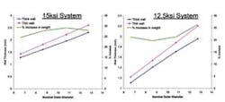
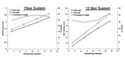
Wall thickness. Determination of accurate wall thickness is a critical first step in design. For HP/HT, the use of Barlow's equation per 30 CFR Part 250 Subpart J may not be appropriate for wall thickness determination considering nonlinear hoop stress variation across thick wall. This may result in an overly conservative wall thickness. Based on recent project experiences, thick wall (>1.6-in.) may pose feasibility issues in terms of procurement and fabrication as well as mechanical property and fatigue performance. Riser weight is also a challenge for deepwater applications. Hence, a more appropriate step to determine wall thickness would be either API RP 1111 or ASME B31.8 (2007).
The API RP 1111 philosophy centers on a limit state approach, whereas the ASME equations are based on an assumption of nonlinear hoop stress distribution across thick wall pipe. Clearly, besides procurement, material property, and fabrication issues, the use of thin wall theory could result in 20-30% higher payload to be carried by a floater.
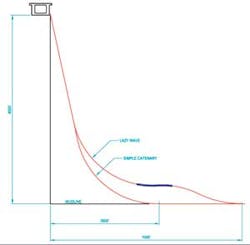
Riser configuration selection, simple catenary versus lazy wave, can make a significant difference in achieving feasibility of SCR application. The critical design issues with simple catenary configuration in deepwater are compression near touch down point (TDP) in extreme and survival environmental conditions, and fatigue damage at/near the hang-off location and TDP.
The compression issue is more common with floaters such as semisubmersibles and deep-draft semis. Compression with a spar may not be critical because of less heave motion compared to a semisubmersible or deep-draft semi.
A mitigation strategy for compression has to be developed since there is no clear acceptability criterion in the API or other industry guidelines. It is important to understand the implications of compression in SCR system design. Riser designers typically attempt to avoid the compression issue. A limited amount of compression within elastic range of material is probably not a concern. However, when the von Mises stress is near or exceeds yield stress, it is advisable to either avoid the condition or use a refined modeling technique using elastic-plastic material and assess actual strain in the system to better understand the dynamic behavior. A plastic strain of small magnitude may influence the integrity of the system and a proper judgment should be made while determining acceptable plastic strain level.
The other option to mitigate compression near TDP is to adopt a lazy wave configuration. A lazy wave configuration has enough flexibility to mitigate compression in a system and is expected to improve fatigue design by a significant margin. However, a proper assessment of buoyancy requirement and associated fatigue damage is necessary where a riser is used to transport multi-phase fluid. In addition, validation of dynamic behavior of a lazy wave SCR may be required, especially in vortex induced vibration assessment.
The other critical concerns from the strength design perspective are related to the hull/pontoon interface. The hang-off selection affects riser hang-off performance in terms of payload and moment, and hence, has a direct impact on hull interface design. For a newbuild hull, the interface issue may be addressed without much difficulty. However, tieback to an existing porch and hull may pose some design challenges due to limited load and moment capacities of the existing interface design.
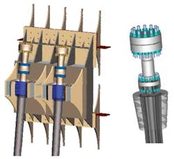
Hang-off design. Appropriate hang-off system selection is important to support the HP/HT SCRs. Hang-off system design for semisubmersible and deep-draft semisubmersible is influenced by both strength and fatigue design acceptability criteria. Several design aspects including hang-off location, hang-off angle, azimuth, and specifically selection of hang-off system such as flexjoint or stressjoint contribute to the overall design strategy of hang-off system. The hang-off system is a critical component in a SCR system, and integrity and reliability should be assured throughout design life.
Hang-off location. To minimize the effect of vessel motion transfer to hang-off, an effort should be made to identify a sweet spot for riser hang-off. This hang-off location should be agreeable to all stakeholders (e.g., subsea, hull, and installation). More often a riser designer has limited flexibility in selecting a favorable hang-off location. The riser heading is controlled mostly by manifold/well location, interference issues, and lifting zone. The safety issue associated with living quarter and boat/vessel approach area further limits flexibility in finding a hang-off location favorable to riser design. Therefore, it is prudent to consider this key item in the early stage of a project, and an effective interface system must ensure that all stakeholders' considerations are properly addressed.
Either flexjoint or stressjoint may be selected, although each system has unique design requirements. Industry experience indicates that the final selection of flexjoint or stressjoint is influenced by the hull/pontoon interface design, technology maturity, and fabrication, transportation and installation acceptability criteria. The flex-element design for an HP/HT environment and its integrity in high temperature are keys that warrant proper qualification early.
Recent flexjoint incidents indicate proper selection of the flex elements and adequate qualification are key to successful implementation and operation. So far, only a few flexjoints have been delivered for high-pressure and temperature exceeding 10,000 psi and 200º F.
Among the critical components of the flexjoint, the most important is the flex element which consists of alternating layers of elastomer and steel reinforcements integrally bonded together with the body and the extension to form a single unit. Elastomer performance at elevated temperature and pressure is the most important qualification requirement of flexjoints and it helps assure the structural integrity of the component during riser design life. Selecting the right elastomer is involved.
First, lab scale tests including ultimate shear, 90° peel, and compression disk testing at various temperatures are performed. Final selection is done after completing a pre-determined fatigue cycles at an elevated temperature during the full-scale prototype test. The maximum allowable elastomer strains are based on flex element design experience, lab-scale tests and the full-scale prototype testing. Early involvement of the potential vendor would help determine the qualification effort that may be required for the specific project.
The titanium stressjoint is another solution for semisubmersibles or deep-draft semisubmersibles; however, it may impact porch/receptacle/pontoon design due to higher moment transfer. Further, lack of full-scale fatigue data as well as NDE inspection constraints of the current NDE tool may limit use of titanium stressjoint. Proper qualification of titanium stress joint fatigue performance using full-scale test samples and the NDE equipment may be prohibitively long. Another supplementing method may be considered to ensure long-term integrity of the component.
It should be noted that the flaw size may be controlled to acceptable criteria by controlling weld pass thickness to 1 mm near root and cap. Low alloy steel (X65 grade) stressjoints are not feasible because of fabrication and installation issues due to significantly large size.
Flow assurance design
Flow assurance design also is critical in designing riser system. For a wet insulated system, the insulation thickness is controlled by the requirement to meet hydrate and wax mitigation strategy during various phases of field life, including shut-down and start-up. However, use of insulation often results in a low submerged weight-to-diameter ratio for the SCR. One challenge in use of a thick insulated pipe is in meeting the fatigue requirement near TDP where fatigue damage due to vessel motions is critical.
Consequently, the hang-off angle has to increase to improve the motion-induced fatigue performance of an SCR near TDP. In addition, a SCR with low submerged weight to diameter ratio is challenging from the perspective of interference with an adjacent SCR. In deepwater, interference/clashing between two SCRs may be critical in the presence of extreme loop or submerged current. Therefore, careful consideration of insulation optimization is necessary to satisfy both flow assurance and riser fatigue/interference performance.
Geotechnical assumptions
Soil/pipe interaction is very complex. Soil/pipe response is sensitive to large and small sea states/offset, seabed trenching, soil nonlinearity, etc. Appropriate geotechnical modeling is critical to accurately assess overall fatigue damage near TDP. It is important to capture soil/pipe interaction accurately to reliably estimate fatigue damage. Typical design practice in early stage of project is to model soil using a linear spring model based on hard seabed. This may be overly conservative assumption. Further, recent studies and experiments show that the use of linear spring model based on hard sea bed assumption is likely to affect SCR feasibility.
Fatigue assessment
Fatigue assessment of SCR is the most critical step in a concept feasibility assessment. A significant effort usually is required to qualify the welding procedures to be used to connect the pipes. This may require significant project time as the wall thickness of riser pipe increases and the material properties, including yield strength, toughness, etc., across pipe wall exhibit more scatter. Therefore, pre-qualification of the potential pipes from mills and welding vendors is recommended. This is especially true for service in a sour environment as a proper knock-down factor needs to be established.
To understand the fatigue performance of a girth weld at the inner diameter (ID) and outer diameter (OD), it is important to conduct full-scale fatigue test in air and environment, so an acceptable S-N curve can be established. It is likely that the fatigue performance based on failures initiated at ID and OD will exhibit some differences. A test frequency scanning is necessary to assess the frequency impact on full-scale fatigue test. If reservoir souring due to presence of H2S is a possibility, a detailed corrosion fatigue assessment should be supported by appropriate crack growth assessment. Corrosion can either affect fatigue crack initiation (e.g. cracks can initiate at corrosion damage such as pits) or can accelerate the fatigue propagation of existing cracks. Mostly SCR fatigue damage near TDP is influenced by low stress ranges and large number of cycles where limited amount fatigue data in environment is available. The best approach during the feasibility stage would be to use a single slope fatigue curve and use a knock down factor properly based on the sour level and available test data. If corrosion fatigue impact is critical, a clad design may need to be considered to isolate the carbon steel pipe from the sour environment. This is more robust than relying on specific operation strategy such as vessel relocation to constantly shift the TDP for improved fatigue performance. For clad design, an appropriate welding qualification should be conducted and a flaw NDE inspection procedure should be established and qualified.
Acceptance criteria
It should be recognized early that the weld requirements need to be achievable and that inspection of the acceptable flaw sizes is achieved based on established NDE technology. An engineering criticality assessment (ECA) usually is conducted using extreme stress and fatigue stress histograms with conservative fatigue crack growth rates to establish initial acceptable flaw sizes. Project-specific crack growth rates based on test results should be required if H2S is possible. Inspection sizing error needs to be added to acceptable flaw. To minimize stress concentration and maximize acceptable flaw size, the weld misalignment should be kept to a minimum. Hi-Lo criteria of 0.5-mm to 0.75-mm are typically achievable to maintain a minimal stress concentration factor (SCF).
It should also be noted that specification of a tight WT tolerances and counter boring at pipe-ends may be required to control the SCF value. This strategy has been proven to improve fatigue life significantly. However, procurement with tight tolerances as well as pipe sorting and end-matching during fabrication tends to increase execution and installation cost.
Listen to a webcast about steel catenary risers for HP/HT applications
A recent webcast investigates why steel catenary risers (SCR) have emerged as an attractive solution for subsea field development of deepwater offshore development. The notable advantage is the reliability and integrity of system over field life with relatively lower cost.
However, the recent exploration success of high-pressure (up to 15 ksi) and high-temperature (up to 250º F) reservoirs (HP/HT) has posed design challenges in terms of fabrication of thick-walled pipes, riser hang-off system selection, and long-term fatigue design. These challenges are exacerbated when the application is associated with floating structures.
Dr. Rupak Ghosh, riser/flowline lead engineer, ExxonMobil Development Co., recently participated in a webcast which focused on HP/HT SCR design. Using case studies, Ghosh discussed the proposed design philosophies and compared them to general design philosophies adopted by the offshore industry.
To listen to the webcast, go online tohttp://www.offshore-mag.com/webcasts/offshore/2012/02/steel-catenary-risers.html.
Acknowledment
Based on a paper presented at the Deep Offshore Technology International Conference & Exhibition, held in New Orleans, Louisiana, Oct. 11-13, 2011.
Offshore Articles Archives
View Oil and Gas Articles on PennEnergy.com


