Developing flow assurance strategies for long-distance tiebacks
M-K. Decrin
E. Sibaud
S. Anres
Saipem SA
L. Rivière
Total SA
The tieback of new fields to existing facilities can be used to develop marginal offshore fields, which are often too small to be developed economically on their own. The use of subsea technologies and innovative field architectures as development solutions is fast becoming a reality. However, long subsea tiebacks come with inherent challenges. The most demanding are the flow assurance issues arising from the different operating regimes, but these may be combined with more viscous fluids and/or reservoirs at low pressure or low temperature.
The goal here is to examine the drawbacks, limitations, and advantages of various field architectures that may be considered for long satellite tieback lengths in deep waters. In this process, it is necessary to cover the different production phases, from routine production to restart, focusing on a flow assurance perspective. The first part addresses production considerations such as turndown, preservation, and restarts for each candidate architecture under normal operation and raises such questions as: what is the impact of tieback length on operating modes? How can new flow assurance strategies increase the operating envelope? The second part examines the impact of these operating modes on the host facilities, addressing such issues as how to deal with greater volumes of oil and which architectures consume less energy.
Future prospects
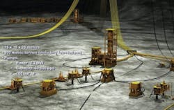
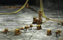
In West Africa and the Gulf of Mexico, numerous fields are to be developed over the next four or five years in water depths ranging from 1,000 to 2000 m (~3,200 to 6,500 ft) and more. The change though is that these latest prospects raise new technical challenges. The reserves are often too small to justify a stand-alone development. Therefore the reservoirs will have to either tie-back to existing facilities or be grouped to create new hubs. The main issue becomes how to transport moderate flowrates of multiphase fluid over long distances. The most notable challenge deals with the flow assurance considerations associated with shutdown management or restart operations.
In addition, the oil characteristics may not help matters when either the reservoir embedment is low, with low temperatures and low pressures at the wellhead, or the fluid viscosity is high, especially if the fluid is prone to emulsion. In some cases, the production fluids have a wax content that makes wax a more critical criterion than hydrates.
Finally, these new discoveries may be located far from shore in deeper and deeper waters.
Selecting the right technical solution is a multi-parameter exercise which systematically entails thorough concept screening and case-specific conceptual studies be initiated well ahead of project sanction.
These require knowledge and experience in the following four areas:
- Subsea architectures: Encompassing the options for manifolding the wells, and development configurations such as the conventional loop, single line, hybrid loop
- Subsea process technologies: Covering subsea boosting, subsea separation (gas/liquid or liquid/liquid), subsea monitoring and control
- SURF technologies: Spanning the solutions for the thermal insulation and electrical heating and the mechanical design of the flowlines and risers
- Deepwater methods and equipment including installation vessels and methods, maintenance vessels, and specific tools such as ROVs and AUVs.
Case study definitions
An example is given here to illustrate the advantages of developing fields with new operating strategies. The values presented are for a generic offshore development. The purpose is to:
- Pinpoint the limits of existing flow assurance strategies
- Identify new architectures and new flow assurance approaches,
- Compare and illustrate the performances of several configurations for a development in 1,500 m (~5,000 ft) of water, through a case study.
It is important to stress here that the results are given by way of indicating a tendency, as they would be different with another crude oil composition. Two common types of crude oil were considered. The base assumptions are given in the table. The total liquid flowrate in the example is of 60,000 b/d.
Review of field architectures
For these two base cases, the following architectures were investigated.
Conventional loop
The most common architecture used to develop deepwater fields is a production loop comprising two separate insulated production lines connected at the manifold. Under normal operation, production is split between the two. During a shutdown, dead oil is circulated in both lines to displace the live oil.
Another solution for low flowrates and/or long distances consists in producing through just one production line.
Single production line
This configuration consists in sending the entire production through one dedicated, insulated line. The line is looped with a service line for pigging, fluid displacement and warm-up operations. This is the architecture in use today on Greater Plutonio and on Marimba where the single production line is looped with a methanol service line.
To reduce the preservation sequence in the event of shutdown, one possible upgrade alternative would be to implement a subsea pigging unit at the production flowline end termination instead of launching the pig from the topsides facilities.
Electrical heating
Thermal management is a key issue in long tiebacks, and the use of electrical heating can be considered as an alternative to fluid circulation for preservation purposes.
This configuration consists in heating electrically a single production line for one of several possible operating modes:
- Temperature-maintainenance under normal production
- Temperature-maintainenance during short shutdown (preservation procedure)
- Remediation.
A number of different technologies are currently under development or already field-proven for preservation and remediation:
- Direct electrical heating (DEH): Asgard (Statoil), Olowi (CNR)
- Heat tracing with PiP: IPB on Dalia project (Total)
- Induction.
However, these solutions dealing directly with the multiphase fluid are quickly limited due to power requirements, voltage level, energy efficiency and installation concerns. Another way of managing the challenges of long, deepwater tiebacks is to modify the fluid to bring it back within the scope of well-known technologies (management of single-phase fluids for instance) or to lessen the extent of the previous requirements.
Gas/liquid separation
Fluid composition can be modified to meet these challenges. One option is to separate oil and water from gas by subsea processing at low pressure in which case fluid can circulate at a temperature below that of hydrate formation.
The separator can be located at the riser base or the wellhead, depending on the pressures available, the tieback length, and slope. The goal is to mitigate the hydrate risk after the separation, to remove gas so as to reduce heat losses, and to achieve efficient liquid boosting.
Several current projects have opted for different technologies such as:
- A vertical separator vessel on the Pazflor project
- A vertical pressure vessel on the Perdido/BC10 field development
- VASPS technology, based on a helix with an ESP on the Marimba field.
Nominal production
Before considering all the transient operations modes, we need first to be clear about nominal production because the type of scenario and fluid composition will impact the hydraulic sizing and the system’s thermal performance.
For all configurations, but especially when dealing with long tiebacks, subsea multiphase boosting at the wellhead is required. Riser-base gas-lift does not significantly decrease the back-pressure on the wells, and is therefore combined with multiphase boosting. Associated control and power supply has to be considered.
Conventional loop vs. single line, impact on hydraulic behavior.
In the conventional loop, the production is split between two lines, offering flexibility for operation according to well pressures, whereas in the single line, the whole production is mixed and sent through one dedicated line.
Two 10-in. lines are therefore mandatory for the conventional loop, one 12-in. line for the single line in the studied case.
Nominal production with gas/liquid separation located at the riser base differs, as the separator pressure will dictate the pressure drops on the upstream multiphase line.
Typical hydrate curve.
The ensuing advantages are as follows:
- When the gas is removed, only the liquid with a low residual gas fraction has to be pumped, which makes the pumping much more efficient,
- With low-pressure separation, counter-pressure will be lower, positively impacting the recovery factor
- Removing the gas also reduces heat losses; the liquid stays at a temperature high enough to prevent hydrate and wax formation that might restrict or stop production under steady-state conditions
- Flow instability issues like severe slugging are eliminated
- The primary separator on the floating facility can be downsized.
After separation, the liquid is boosted with a gas-tolerant liquid pump to the facilities.
To take advantage of the gas/liquid separation scenario, the separator can be located near the wells and operate at low pressure. This calls for long-distance liquid boosting. Depending on the separation pressure, the gas may either flow freely or require compression.
The downside of this configuration is that transmission and distribution of power, like control and monitoring, may be a challenge for very long tiebacks.
The table presents the impact of the scenarios on the U-value requirement on a 70-km (~44-mi) production line; all the designs are driven by the U-value. The interest of using subsea processing to extend the possibilities of development is plain.
Current projects achieve a U-value of 0.7 W/m2/K and lower values are feasible but need more development.
Continuous (permanent) electrical heating for instance can also be considered with the single line, removing the stringent thermal constraints and opening up prospects of developing very long tiebacks. Energy efficiency and power consumption depend extensively on the technology (DEH or traced PiP) employed. The reliability and reparability of the electrical devices are crucial questions.
Nominal production mainly impacts hydraulic design. Depending on fluid properties, the turndown flowrate coupled with low water-cut may be critical as regards thermal constraints.
Turndown management
During a production turndown, the reduction in total heat-flow into the system causes the temperature to drop into the hydrate formation region. Chemical injection may be the first option to consider but for long step-outs, the inhibition requirements and corresponding storage capacities are not viable.
The scenarios can soon be limited due to thermal constraints imposed by the flowrate.
For a conventional loop, the limit is reached for a step-out of 40 km (25 mi), assuming a maximal value of 0.7 W/m2/K. The single line looped with a service line can achieve slightly longer tie-back lengths. The gas/liquid separator, if located at the riser base, can be placed as far as 70 km (44 mi)away provided an acceptable back-pressure is ensured on the wellhead.
Electrical heating is a feasible solution but can be highly power-consuming, depending on the technology.
Shutdown management
Shutdowns may, of course, be planned or unplanned but whatever the prime concern, the production lines should be preserved to mitigate the hydrate and wax risk. This, however, entails severe constraints on the architecture.
Live oil displacement
In a conventional solution, the live oil is displaced with dead oil from the topside facilities. According to our case study, for two 10-in. production lines over 30 km (~19 mi), it takes 3000 cu m of dead oil to displace the produced fluid over that distance. This means dedicating substantial storage volumes of (wax-free) fluid for the purpose. The single line looped with a service line uses the same principle as the conventional loop for its own preservation, hence the same cool-down time requirement. To decrease the cool down time, especially when it is the design driver parameter, the use of a subsea pig launcher merits consideration.
Active heating
Temperature can be maintained above the hydrate formation region during a shutdown by electrical heating. The best technology and method will be determined on the basis of cost and energy efficiency. If used for preservation, essential power generation will need to supply the duty required to last through an unplanned shutdown.
Flowline depressurization
The objective of the depressurization is to bring the line out of the hydrate area at ambient temperature.
The pressure levels in the flowline after depressurization will depend on the bathymetry and tieback length.
Typical warm-up profile along a production line.
Shutdown operations for architectures with gas/liquid separation are based on depressurization of the separator and the multiphase line through the gas riser. In the case of a separator located near the riser base, two possible cases must be addressed:
- An uphill slope downstream of the separator: if the inclination is too steep, the backpressure will be too high to remain outside the hydrate formation area. Heating of the liquid column could be used here to avoid the risk zone
- A downhill slope downstream of the separator: the liquid will drain to the separator and be pumped to the topsides facilities with the subsea boosting equipment. This configuration appears clearly favorable.
Warm-up and restart
After a shutdown, production can only be restarted if the temperature in the system is high enough to avoid entering the hydrate stability zone. Otherwise, the system has to be pre-heated by circulating hot fluid through the line until an acceptable thermal level is reached.
The warm-up operation can be long, depending on pipeline length and the thermal inertia of the insulation.
Hot dead oil circulation
In the conventional loop and single line looped with a service line, hot dead oil circulates from topsides in the production lines. The longer the tieback length, the higher the initial dead oil temperature must be to warm the pipe and the longer the flowline will take to warm.
The research showed a warm-up profile on a 20-km (~12-mi) tieback reaching a safe temperature after 20 hr. For this operation, 30,000 bbl of dead oil are required to warm the line. Substantial storage and topsides boosting capacities have to be taken into account when connecting a new development of this type to the host facilities.
Chemical injection
Configurations with a gas/liquid separator comprise only one multiphase line (no service line needed). Another approach excluding fluid circulation can be considered.
Restart with injection of inhibitors like methanol coupled with a long ramp-up and start-up at low pressure are one possibility. The time it takes to warm up the line before chemical injection can be stopped will be long for long distances. The quantity of chemicals will also depend on the water-cut in the produced fluid.
Electrical heating
With an electrically heated system, the wells can be restarted directly, as the production line is already warmed and DEH offers extensive flexibility in managing such operations, as the system is ready to start. Nevertheless, it demands highly reliable electrical devices, as there is no back-up.
Impact on host facilities
The management of transient operations has a substantial impact on the host facilities.
The conventional loop and single line looped to a service line require dedicated storage of wax-free dead oil and a recirculation pump to ensure efficient preservation and warm-up.
Essential generation should ensure:
- Topsides boosting for the conventional loop and single line looped to a service line
- Power supply for the electrical heating system, for scenarios assuming this preservation mode.
Electrical power and power transmission systems have to be installed on the facilities for electrically heated configurations.
For a gas/liquid separation scenario, provision must be made for large chemical storage capacities (thermodynamic or LDHI) and a dedicated circulation pump for chemicals.
Production considerations
The power to be supplied on the topsides during routine production will differ depending on the scenario. Our analysis compared various scenarios for a 20-km tieback, assuming the conventional loop as reference case. Only the DEH system presents significantly higher power needs, as the electrical heating is coupled with wet insulation. Heat tracing is unnecessary as an efficient pipe in pipe is enough to ensure the minimal thermal requirements.
One scenario involved a 70-km tieback length; it was selected to emphasize the impact of the new scenarios on power consumption under normal production conditions. The conventional loop and single line looped to a service line are shown, with thermal limitations corresponding to current passive technologies.
DEH systems require four times more power than a conventional loop as they are combined with wet insulation. PiP coupled with heat tracing consumes less power than DEH. Installation constraints and reliability of the electrical devices are the crucial issues on these technologies.
Conclusion
As step-out distances become longer and fluids more challenging, the limitations of conventional tieback technologies become greater and the costs (both capex and opex) higher. The distances are limited by constraints centering on the fluid properties.
Subsea processing and other innovative subsea configurations considerably extend the potential step-out length (up to 100 km, or about 60 mi, in favorable cases). These long tie-back developments therefore include subsea processing, bigger pipe diameters or electrical heating systems, all of which strongly affect installation capabilities and procedures.
A cross-disciplinary organization composed of several competencies working to understand and cover the whole scope of work for screening studies is therefore a definite plus point, allowing comprehensive optimization of the solutions. This is critical to enhance the economical viability of these satellite fields and above all to reduce the risks related to the interfaces.
Acknowledgement
Based on a paper presented at Deep Offshore Technology International held on Nov. 30-Dec. 2 in Amsterdam.
Offshore Articles Archives
View Oil and Gas Articles on PennEnergy.com


