Deploying hybrid riser solutions for harsh environments
Kjell Hagatun
Aker Solutions
Oddrun Steinkjer
Det Norske Veritas
Halvor Lie
MARINTEK
Two joint industry projects (JIPs) recently examined the use of deepwater hybrid risers for harsh North Atlantic environments.
The first JIP targeted development of a hybrid riser based on known technology to use in Norwegian deepwater fields. Fatigue during installation initially was considered to be the most challenging obstacle. Good fatigue design and low fatigue load installation were governing goals for the concept definition phase. The resulting concept is a bundled riser tower fabricated onshore and towed submerged to the field. Tow out, upend, and installation can be done with three tugboats. The riser tower was defined for a case study with a large oil field at 1,500 m (4,921 ft) water depth.

The second JIP showed that long, slender riser towers can be transported safely offshore by submerged tow. Two model tests were done – a tow test and a vortex induced vibrations (VIV) test. The tow test was done in still water, in waves with 3-m (9.8-ft) significant height, and 10-year summer storm conditions. The VIV test was in steady current with different speeds and inclined angles relative to the riser tower. The 1,300-m (4,265-ft) long riser tower was modeled in scale 1:38.6. Instrumentation included fiber optics to measure bi-axial bending strains at 20 locations along the riser bundle.
The measured responses were also used to validate the analysis models applied to calculate tow resistance, wave induced dynamics, and VIV.
Recent development of hybrid risers in West Africa proves it successful for deepwater fields with demanding flow assurance challenges3, 4, 5, 6. The main advantages of hybrid riser systems are:
- Riser tower motions are decoupled from floater motions, reducing stress and fatigue problems in the riser system
- Flow assurance can be achieved by thermal insulation, gas lift, and active heating
- Bundled hybrid risers have small footprints and no interaction problems with flowlines and mooring lines
- Schedule flexibility with pre-installation of hybrid risers
- Increase local content by fabrication and assembly at local yards.
Fatigue during tow out and installation was the main challenge to adapting this technology to North Atlantic environments. Low fatigue load governed selection of a bundled hybrid riser and submerged tow.
The JIPs were funded by Demo 2000, Statoil, Shell Technology Norway, Aker Solutions, Det Norske Veritas, and MARINTEK. Aker Solutions was responsible contractor with Det Norske Veritas and MARINTEK as cooperating contractors.
Hybrid riser description
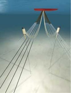
A hybrid riser system with a turret moored FPSO on a large oil field in 1,500 m (4,921 ft) water depth was the study case. The riser consists of two free-riser towers, the flexible risers between the towers and the FPSO, and the spools connecting the risers to the seabed flowlines.
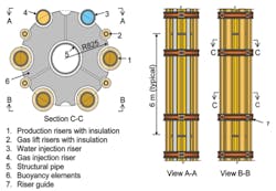
The two riser towers are identical. Each contains four production risers with individual gas lift lines and two injection risers. The main components of a riser tower are the riser bundle, the top assembly with buoyancy tank, and the bottom assembly. The riser towers are fabricated onshore, towed to field, upended, and connected to pre-installed anchor foundations at seabed.
The long, slender riser bundle contains risers, a central structural pipe, and buoyancy elements. The bundle concept has the following features:
- The external risers are fixed at the top and can slide axially to accommodate thermal expansion. The production and gas lift risers can be thermally insulated.
- The center pipe is the structural load carrying element between the buoyancy tank and the anchor foundation.
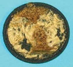
- Buoyancy elements molded from syntactic foam ensure that the riser bundle is approximately weightless in water during tow and upending.
- Guide rings around the buoyancy elements keep the bundle parts together and allow riser pipes to slide axially.
- Elastomer bearing pads go between the rigid buoyancy sections to allow for a bend in the riser bundle.
- Several bulkheads along the riser bundle to transfer the uplift forces from the buoyancy elements into the central structural pipe.
For the case study, the riser bundle was about 1,200 m (3,937 ft) long with a diameter of approximately 2 m (6.5 ft).
The buoyancy tank must carry the submerged weight of the riser tower and flexible risers, and limit the offset/angle of the tower due to environmental forces. The buoyancy tank is positioned about 200 m (656 ft) below sea level where the wave loads are moderate, even in severe storm conditions. The compartments are soft tanks that are 100% water filled during tow out, upend, and installation. After the riser tower is connected to the foundation, the compartments can be air filled as necessary to achieve the target net buoyancy. For the case study the tank was sized to provide up to 1,600 metric tons (1,764 tons) net uplift during service.
The proposed tow out and upend requires the tank to have constant net buoyancy during these temporary conditions. This is achieved by adding buoyancy elements made of syntactic foam at the top and bottom.
The riser tower is anchored to the seabed foundation by a flex joint that allows the riser tower to tilt as much as 10º in any direction. The foundation can be an anchor pile or a gravity based structure.
The hybrid riser system was subjected to comprehensive analysis for the in-place condition. The analyses documented that the dynamic response in the tower is relatively small, and is due mainly to motion of the flexible jumpers as introduced by FPSO motions. The resulting stresses in the riser tower were manageable for both extreme loads and fatigue loads.
Hybrid riser systems can serve a range of deepwater fields developed by FPUs. Fluid transfer capacities can be adapted to field requirements by changing the number of riser towers, and the type, size and number of risers. With a turret-moored FPSO, the maximum riser number is limited by the turret and swivel.
Tow out, installation
Tow-out and installation of the riser tower are designed for long-distance offshore tows and a 10-year summer storm in the Norwegian Sea.
Early in the project it was concluded that submerged tow was the only feasible transport method for bundled riser towers over long distances in harsh environments. Submerged tow of riser towers had been proposed by others2,7, and recently the Greater Plutonio riser tower was installed successfully by the submerged tow method.6
The main principles for submerged tow in harsh environments are:
- The long riser bundle is near neutrally buoyant in water and is tensioned by two tugboats
- The forward and aft tanks are buoyant with net uplift to support heavy chains connected to tanks tow lines
- Towing depth is controlled by the leading and aft tugs adjusting tow line lengths and pull forces.
The riser tower is towed with the large buoyancy tank forward. For the case study, a back tension of approximately 1,000 kN was assumed, and the forward and aft buoyancy tanks had a net uplift of typically 60 and 40 metric tons (66 and 44 tons), respectively.
In survival and temporary conditions, the riser tower can be parked by lowering the aft end until parts of the heavy chain rests at seabed. With a slightly buoyant riser bundle, the tower can also be parked by lowering the forward end.
The submerged tow method for riser towers has the following advantages:
- Tow-out, up end, and installation can be done by three offshore tugs
- Few operations between inshore tow, offshore tow, and upend
- The riser tower behaves well with low bending even in storm conditions
- A survival condition is easy to accommodate
- Fatigue management can be incorporated by adjusting the towing depth, towing speed, tow heading, and parking for survival conditions.
The offshore upend and installation can be done similar to the riser towers installed in Africa.6
Model tests
The model tests of the hybrid riser tower were done by MARINTEK in Trondheim, Norway. Two test campaigns were performed:
- Towing tank tests studied behavior during normal towing conditions, 10-year summer storm, and some accidental conditions
- VIV (vortex-induced vibration) tests in the ocean basin investigated VIV during tow.
The principle arrangement for the tow test comprised the submerged riser tower, two towing line/chain systems, and two tugs connected to the two carriages.
The model set up for the VIV test was a submerged riser and two towing line/chain systems suspended between two gondolas. Constant back tension was achieved by a weight-pulley system mounted at the “aft” gondola. The current in the ocean basin is in one direction so the riser tower model was rotated to get the specified angles between the tower and the incoming current.
The riser tower and the chain/wire towline system were modeled with correctly scaled dimensions, mass, and buoyancy. The riser bundle also was built with correctly scaled bending stiffness. Two identical tug models were made for the tow tests.
After launching the model in the towing tank the weight was adjusted slightly to achieve correct submerged weight with nearly neutrally buoyant riser bundle.
The riser bundle was instrumented with fiber optics at 20 locations to measure axial and bi-axial bending strains. The towing test was instrumented to measure wave elevations, towing speed, tug motions, vertical motions of riser tower buoyancy tanks, and forces in towing and mooring lines. In the VIV test the current speeds were measured to compare with the calibrated speeds.
Tow test
The test program for the riser tower in the tow tank included:
- Towing in still water with speeds of 0.5, 1.0, 2.0, and 3.0 m/s (1.6, 3.28, 6.5, and 9.8 ft/sec.)
- Towing in waves with 3 m (10 ft) significant height with the same towing speeds
- 10-year summer storm with both tugs connected
- 10-year summer storm with bottom end parked above seabed
- Simulating parking for survival conditions
- Simulating accidental conditions with increased weight (leak) and aft tow line break.
The fatigue analysis of the measured bending stresses along the riser bundle showed very low fatigue damage. The riser tower could be towed for several months in sea states up to 3 m significant wave height.
The tow tests demonstrated the feasibility of the submerged tow method:
- The towing operations can be controlled by adjusting riser tension, tow depth, tow speed, and tow direction
- The riser tower can be safely parked with bottom chain lying at seabed. Furthermore, the building of riser tower model illustrated the importance of accurate weight and buoyancy control during fabrication, and final adjustment of submerged weight after launch.
VIV test
The program for VIV tests in the ocean basin included tests with:
- Current speeds ranging from 0.3 m/s to 1.1 m/s (1-3.6 ft/sec.)
- Current angles between zero and 90º
- Constant back tension of 1,000 kN (base case) and 750 kN.
At zero heading, no VIV was observed. For all other tests, resonant cross flow vibrations of the riser tower were observed with amplitudes around one diameter. The highest responses appeared at the aft end with the smaller buoy. The periods of the eigenmodes excited were typically between 10 and 20 seconds.
The highest standard deviation of VIV cross-flow bending stresses along the riser in each test was plotted against current speed and angle for the tests with 1,000 kN back tension. The highest standard deviations were measured with 0.6 m/s current speed at 90º angle and the test with 1.0 m/s speed and 30º angle.
Fatigue calculations for the central structural pipe used the measured standard deviations of VIV bending stresses. The critical hot spot was the inside (root) of the single sided girth welds where the DNV F3 S-N curve in air were applied in combination with a stress concentration factor (SCF) of 1.0. This approach is considered conservative since the fatigue strength of the actual girth welds probably is significantly better than the F3 curve (which also includes a SCF of 1.61, ref. DNV-RP-C203, Table 2-1).
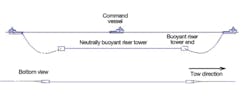
Illustration of submerged offshore tow method.
The riser tower must be designed with a factor of 10 on fatigue life, i.e. the accumulated fatigue damage must be less than 0.1. Assuming that maximum 50% of the damage can occur during tow-out gives a maximum allowable damage of 0.05 for the tow-out fatigue calculations.
The resulting highest fatigue damage along the riser for each test with 1,000 kN back tension was plotted as function of current speed and angle. The damages for 24-hour durations of each current condition were used. The highest damage of 0.011 per day was estimated for two tests: The test with 0.6 m/s current and 90º angle and a test with 1 m/s current, 30º angle and reduced back tension of 750 kN. Continuous VIV at this damage rate would be acceptable for many hours but not many days.
The main findings from the VIV tests can are as follows:
- All tests showed moderate stress levels in riser tower
- Negligible fatigue for current speeds below 0.4 m/s for all angles
- Negligible fatigue for current/towing angles below 15º and speeds up to 1.1 m/s
- Current/towing speed of 1 m/s and 30º angle can give moderate fatigue damage
- Reduced back tension gives increased fatigue damage.
Negligible VIV fatigue can be ensured by using good heading control, high back tension, and moderate/low towing speed during the riser tower towing operations.
Hence it can be concluded that the feasibility of the offshore submerged towing method has also been verified with respect to VIV.
Validation of analysis
The model tests also were used to validate the analyses methods and models for calculating tow resistance, dynamic responses, and fatigue damage during tow. VIV predictions for inclined current are of interest as no literature reference was found regarding experimental results to calibrate VIV analysis for inclined current conditions.
The Riflex finite element program was applied for static and dynamic analysis of the riser tower towing operations. In general, Riflex predicts fairly well the measured responses. The dynamic responses of the smaller aft buoy were somewhat lower than the measurements.
Shear7 was applied for VIV analysis. The following observations were made:
- In general, the results from Shear7 analyses using normalized current compare very well with the results reported from the tests
- Analyses with the velocity normalized to the curved tower (banana shape due to static current) tends to flatten the standard deviation of the curvature compared to constant normalized current along the tower. Hence, this case fits best with the model test result
- Using Strouhal number St=0.18 with normalized current on curved tower gives best fit with test results for all cases analyzed.
Acknowledgements
The authors thank Statoil, Shell Technology Norway, Aker Solutions, Det Norske Veritas, and MARINTEK for permission to publish this paper and the Demo 2000 program for its financial support.
The authors are particularly grateful to the JIP steering committee members for constructive discussions and valuable advices and to the project team at MARINTEK for performing the challenging model tests.
References
1. G. Arnesen, J.I. Dalane, S.S.B. Arananadka, K. Herfjord, R. Snell and C.T. Stansberg: “Integrated Semi and Steel Catenary Risers in Deep Water and Harsh Environment Conditions,” OTC 2006, paper 18259.
2. A. Sele, P.K. Løken, R. Thomas and B. Klasen: “All-Metal Hybrid Riser for Ultradeepwater and Harsh Environments,” OTC 2005, paper 17107.
3. A. Serceau and R. Pelleau: “The Girassol Development: Project Challenges,” OTC 2002, paper 14166.
4. J.B. Bates, G.O. Gernon and M.D.A. Gillette: “Kizomba A and B: Installation Overview,” OTC 2006, paper 17941.
5. S. Couprie, R. Hallot, Th. Marty, X. Riou, D. Ferri: “Bundle Hybrid Offset Riser Thermal Performance Test on ROSA Project,” DOT Houston 2006.
6. D. Cruz, C. Zimmermann, P. Neveux and F. Louvety: “The Greater Plutonio Rise Tower,” OTC 2009, paper 19929.
7. R. Di Silvestro, F. Casola, G. Fatica, A. Mameli, and A. Prandi: “Novel Tow Methods for Deepwater Riser Towers Transportation in west-of-Africa Environment,” OTC 2006, paper 17892.
Offshore Articles Archives
View Oil and Gas Articles on PennEnergy.com