The Skarv FPSO turret mooring system: A 5,000-ton challenge
Mamoun Naciri
Christophe Jamet
Renaud Daran
Stein Vedeld
SBM Offshore
Pieter Drijver
Volkert Visser
BP Norway
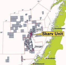
BP intends to develop Skarv field using a turret moored new-build FPSO. The Skarv FPSO has a heading control system because the turret, positioned at 1/3 of ship length aft of the forward perpendicular, has reduced weathervaning characteristics.
The Skarv FPSO station-keeping philosophy addresses both Norwegian offshore regulations and BP’s specific requirements, and contains a matrix of load cases to consider in mooring design. The harsh environment at Skarv, along with specific survivability requirements in black ship conditions (complete loss of power for heading control system), result in mooring loads in excess of 5,000 tons. This is a step-change increase from typical values for existing turret moored FPSOs.
The Skarv internal turret system is suited for high extreme loads. It consists of a large diameter cylindrical turret structure integrated into the hull. In the lower section the chain table houses double articulated chain stoppers to which the anchor legs connect.ed. Mooring loads transfer from the chaintable through the turret cylinder up to the turret main deck and to the vessel via the bogie bearing system.
The axial bogies support the earth-fixed turret weight and vertical loads, and counteract moments. Radial wheels in the bogie support cylinder above the highest water level transfer horizontal loads from the turret to the vessel. In addition to this proven bogie bearing system, an additional lower friction bearing functions when mooring loads exceed a certain level (eg. black ship) to assist the bogie system.
The primary purpose of a floating platform’s station-keeping system is to maintain the platform at its location in the field and to keep the risers and dynamic umbilicals within their design limits, thereby protecting the environment and the safety of the personnel onboard.

On Skarv, the accommodation, with its temporary refuge, is forward on the FPSO, in line with common practice on the Norwegian continental shelf. Skarv is a predominantly high-pressure gas field, so the turret and swivel stack are as far away as possible from the personnel accommodations. Explosion modeling set the optimal layout of the FPSO, and also considered the position of the main power generation module as it is the main potential ignition source. A total FPSO risk review led to a turret position at one-third from the forward perpendicular, behind the power generation module. This means that the FPSO has reduced weathervaning capability.
On the Skarv FPSO, the mooring system and a heading control system together provide overall station-keeping. It is imperative to consider both systems in developing a station-keeping design philosophy and associated operating procedures.
In the extreme weather of the Norwegian Sea, the heading control system will minimize environmental loads on the hull and mooring system. In normal weather, heading control improves personnel comfort by minimizing vessel motions and ensures the vessel heading maintains an angle with the wind direction to optimize natural ventilation of the process modules. Normally, net forward thrust is not be provided. The Norwegian requirements for mooring design call for a two-line failure, so a robust mooring system is required. Operating with one line failed is feasible up to relatively severe conditions.
A design premise for the heading control system is that no single failure makes it impossible to maintain heading. From investigations by Noble Denton into DP failures, it is known that even with redundant systems like that on Skarv, complete failures or blackouts occur. Following advice from Noble Denton, the project includes the ability to survive a complete loss of power for the heading control system (i.e. black ship) in a 100-year storm in a matrix of design cases for the mooring system.
Design criteria
Per the station-keeping philosophy, BP required consideration of three cases beyond the ISO requirements. In particular, the two-line broken case is to be investigated in 100-year conditions to document robustness of the system. Furthermore, consideration of a “black ship” case in 100-year condition instead of 10-year conditions per ISO is included. Finally, a robustness case must be considered in 10,000-year conditions with the station-keeping systems intact (i.e both mooring and heading control systems intact). In these extremely rare conditions, the Skarv FPSO must remain on station, provide a safe shelter to the crew and safeguard the environment. In addition, the project assessed the maximum allowable metocean conditions for a continued production with a single mooring line failure, meeting the required factors of safety for a two-line and three-line failure. The Skarv mooring line shall have a fatigue life of eight times the FPSO service life; i.e., 200 years.
Heading control system
Thrusters assist the natural vessel weathervaning and maintain the vessel so that wind incidence is approximately 15º from portside to enhance ventilation. In storms this requirement can be waived. The use of thrusters reduces forces introduced by wave, wind, and current on the vessel compared to the free weathervaning. Although five thruster units are provided under the hull for heading control, the mooring analyses assume only four are available at any time. Furthermore, the “stand-by” thruster is conservatively assumed to be the most onerous one i.e. that with the largest restoring yaw moment. When considering the “black ship” condition, all five thrusters are not functioning and the station-keeping of the Skarv FPSO becomes fully passive.
Mooring system layout
The mooring system consists of three groups of five mooring lines. The angular spread between each bundle is 120° and the angular spread between two mooring lines within a bundle is 5°.
One anchor line extremity is secured to the seabed with a suction pile. The anchor line consists of three segments: a bottom chain, a 121-mm (4¾-in.) diameter steel wire rope, and a top chain connected at the chaintable. Both chain segments are 152 mm (6 in.) R3S stud-less chains. The steel wire rope comes with a high-density polyethylene (HDPE) protective sheath for long-term corrosion protection. The pretension in intermediate draft is 1,770 kN. The chains and steel wire rope packages are from Vicinay and Parker Scanrope, respectively. The suction piles have been engineered by SEMAR and fabricated by FCM.
Global performance first was assessed during a model test in January-February 2008. Calibration of numerical tools against these model tests validated their use in the definition of the design loads. Design turret excursions occur for low peak wave periods associated with significant wave heights notably lower than the contour maximum. In contrast, design dynamic tensions occur for sea-states close to the contour maximum.
Marine growth has been considered for both extreme and fatigue limit states. The marine growth thickness values specified by default were found early to have significant consequences. Site specific data was collected by BP in collaboration with its Skarv partners to provide more realistic yet conservative depth-dependent marine growth thickness values. The fatigue lives obtained with this field specific data were summarized. Lines 6 to 10 in the south bundle are the most fatigue prone.
The ULS 100-year mooring force corresponds to the contour peak significant wave height. The ALS 100-year mooring force is obtained in 100-year “black ship” condition for Hs=16 m. The mooring forces in ULS and ALS black ship 100-year conditions are respectively 2,900 tons and 5,400 tons. The mooring force in 10,000-year conditions is 4,100 tons. These mooring forces are more than twice the value used to design BP’s FPSOSchiehallion turret in the late 1990s.
Turret system design
The turret is integrated in the fore part of the FPSO, within a moonpool well. It provides the following three critical functions:
- Attachment point to the anchoring system effectively provides one element of the station-keeping of the Skarv FPSO
- It allows the FPSO to weathervane around the earth fixed turret cylinder
- Transfer of production, injection, export, and services fluids through the swivel stack between the earth-bound turret and the weathervaning FPSO.
The bottom parts of the turret consist of the lower turret (including the chain table and the cylinder) and the collar structure (including the collar deck). The turret itself is a steel cylinder inserted in a well, formed around the center line of the vessel, one sixth of Lpp fore of amidships. The turret is supported by the vessel via axial bogie arrangements, at the vessel’s main deck level. In normal conditions, the horizontal loads on the turret are transferred by radial wheels above the maximum draught level.
Axial bogies and radial wheels form the “roller-based bogie bearing system” of the turret weathervaning bearing system. The axial bogies and the radial wheels are based on a proven turret bearing system design (Ref BP FPSOSchiehallion) that has been in operation since 1998 with the harsh operating conditions of the North Atlantic west of the Shetland Islands. This system also was chosen for previous projects (Capixaba FPSO, P53 FPU, Frade FPSO, Espirito Santo FPSO, and Aseng FPSO) where station-keeping is entirely passive.
On Skarv, mooring forces are far beyond any experienced before. Therefore it was decided to implement friction bearing pads with corrosion resistant bearing faces underwater. In extreme conditions they assist the radial wheels and also relieve some of the moments and loads on the axial bogies. In normal conditions these pads are not active so fatigue is not an issue.
This lower friction bearing design is derived from previous projects such as the White Rose FPSO operating since 2004 (other projects using friction bearing are FPSOEspadarte, FPSO Brasil, and FPSO Marlim Sul, P33 and P35).
Weathervaning bearing system
The turret weathervaning bearing system consists of:
- The bogie support structure fitted on top of the vessel well cylinder, which forms the extension of the vessel moonpool
- The bogies that transfer the axial turret loads to the bogie support structure. The bogie wheels run on a rail structure mounted on the underside of the collar deck
- Radial wheels mounted in the turret bogie support structure below the bogies. These wheels run on a rail structure mounted on the turret cylinder
- Friction pads sliding (in extreme conditions only) on an Inconel-overlaid bearing face on the vessel moonpool walls.
In normal conditions (low loads) the radial wheel and axial bogies transfer loads from the turret to the vessel structure. Turret loads are caused by the vessel induced inertia loads, mooring and riser loads acting at the chain table.
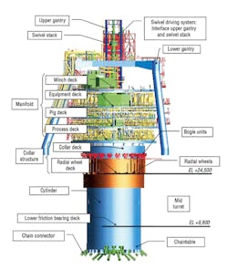
Skarv turret components.
In extreme conditions, the friction pads support a large fraction of radial loads, once the initial gap between the vessel and the friction pad(s) closes.
The radial wheels and axial bogies will be protected against rain by a closure at the top between the turret collar and the vessel upper deck (weather barrage) and against sea water by a lower sealing arrangement. The well sealing is schematically represented in between the radial wheels and the max draught level.
The axial bogies are on elastomeric pads that allow the bogie units to adjust to small (radial) translations or rotations due to angular misalignments or local deflections. A set of guiding wheels mounted on each bogie unit keeps the bogie aligned with the rails on the turret collar.
Both the axial bogies and the radial wheels are installed in such a way that they can be inspected, maintained, or even changed out if necessary.
For axial load transfer, the axial rails are integrated in the underside of an outer supporting ring located below the collar deck. For radial load transfer, the radial rails are on the circumference of the cylinder at the radial wheel deck level. Both rails have segments that can be changed out in situ.
The bogie support structure is integrated in the vessel as close as possible to the neutral line (for overall bending) of the vessel, the distortion of the vessel due to hogging and sagging being the lowest at this level. The bogie support decouples the deflections of the vessel from the bearing arrangement. Consequently the deflections of the bogie support structure at the top are minimal, allowing all the wheels to run on the rails and take their share of the load.
Design analysis methods
The friction bearing system withstands the extreme radial mooring loads. It is made up of friction pads mounted on the turret cylinder and running on vessel-mounted Inconel-overlaid rail structures.
When there are no loads acting on the turret cylinder, there is a nominal gap between the friction pads and the vessel cylinder. When a horizontal mooring force acts on the cylinder, it deforms and eventually the friction pads contact the race on the moonpool wall. The maximum loads on the upper bogies and the radial wheels will be seen just before contact. After contact a significant fraction of the loading is taken by the friction pads.
During extremes the hogging and sagging effects need to be considered. This is introduced in the analyses as a gap variation coexisting with the maximum mooring load. In addition, an integration misalignment (=co-axiality) needs to be represented.
By adding the turret co-axiality and the hogging and sagging effects, two groups of analysis have been performed:
- Maximum gap opening aligned with mooring load to consider the maximum loads on the bogies and radial wheels
- Minimum gap opening aligned with mooring load to consider the maximum loads on the friction bearing system.
In addition the effects of tolerances, deflections, stiffness variations, etc, were accounted for considering the following:
- Machining and construction tolerances of the vertical and radial rails, and the friction bearing system
- Stiffness variations of the bogie supports
- Deformations induced by hogging/sagging
- Bogie set up flatness.
Acknowledgments
The authors wish to thank BP and SBM for permission to share this information regarding the Skarv TMS design. The authors also acknowledge and thank Chris Vogt for his continuous mentoring, guidance, and enthusiasm in the execution of the Skarv project.
Editor’s Note: This is an excerpt from a Deep Offshore Technology International presentation.
Offshore Articles Archives
View Oil and Gas Articles on PennEnergy.com