New vessel designs facilitate offshore pipelay

D.K. Das
Jose Gonzalez
UniversalPegasus International Inc.
Recent advances in pipelaying equipment and vessel design can help offshore operators and contractors overcome challenges posed by uneven seabed terrain, including major sandwaves, outcrops, pockmarks, and general unevenness. As the industry moves into deeper waters, the difficulties posed by uneven seabed landscapes will become increasingly significant, and these latest advances will figure more prominently.
The goal here is to discuss some of the more notable seabed characteristics which could pose difficulty in offshore pipeline and subsea structure installation; and to review some of the latest equipment and technologies than can be used to overcome these challenging offshore terrains.
Sandwaves and outcrops
Sandwaves are large, ridge-like primary structures which resemble water waves and form on the surface of the seabed due to high-velocity water currents. Significant sandwaves are generated where the seabed is predominantly sand or gravel. Sandwaves can form seabed topographies which may be several miles in extent, with the waves in primary and secondary patterns. The waves vary in size from ripples, as seen on a sandy beach at low water, to waves up to 20 m (65.6 ft) in amplitude and several hundred meters in wavelength. The waves forming the primary pattern may be several miles long. They usually lie nearly at right angles to the main direction of water movement. Although the ridges and troughs of sandwaves could be virtually stationary, they are also known to move and alter significantly in height. Subsea pipeline routes are typically selected in a manner which avoids sandwaves, but in certain cases there may be no alternative but to resort to leveling the peaks and/or constructing a trench corridor through the sandwave terrains.

Similar to sandwaves, outcrops of old coral reefs can also pose obstacles to the routing of pipelines. In certain parts of the Gulf of Mexico, such outcrops attain up to 10 meters (32.8 ft) in diameter and two meters (6.56 ft) in height, while ones with smaller dimensions can be spread all over the seabed. Pre-lay of pipelines through areas with outcrops might require their removal to ensure relatively even seabed conditions.
A trailing suction hopper dredger (TSHD) can be used to flatten sandwave ridges or outcrops, and/or to dredge a trench to allow routing a pipeline in areas with sandwaves and outcrops. For example, Van Oord’s (VOO’s) TSHDVox Maxima can dredge in water depths of up to 125 m (410 ft), has a hopper capacity of 31,200 cu m (1.1 MMcf), a maximum dredging depth of 125 m (410 ft), and an operational maximum draught of 14.5 m (47.5 ft). Tideway, a member of the DEME Group based in Belgium, says its TSHD, Brabo, can be used in up to 43 m (141 ft) of water. Jan De Nul has several TSHD vessels; among these, Vasco Da Gama has a maximum dredging depth of 140 m (459 ft) and Cristóbal Colon 155 m (508 ft). The hopper capacity of Vasco Da Gama is 33,000 cu m (1.16 MMcf) while that of Cristóbal Colon is 46,000 cu m (1.6 MMcf). Royal Boskalis Westminster nv’s (Boskalis) Queen of the Netherlands TSHD vessel can execute work in water depths of over 150 m (492 ft).
Project application
Boskalis’Queen of the Netherlands removed 188,000 cu m (6.6 MMcf) of soft soil and boulders principally along a 2,800-m (9,186-ft) long trench for a 42-in. gas pipeline between Norway and Germany in work related to the Europipe 2 project. The same TSHD was used in 1999 to excavate five 10-m (32-ft) deep glory holes at average water depth of 96 m (315 ft) in the Terra Nova offshore oil field, approximately 200 nautical miles southeast of St. John’s, Newfoundland. (Glory holes are artificial depressions made on the seabed to protect wellheads from potential iceberg damage.) Later in 2003, Jan de Nul’s Vasco Da Gama was used to excavate Husky Energy’s White Rose glory hole at 130 m (426 ft) water depth offshore Canada’s East Coast.
Pockmarks
Pockmarks are the most common hydrocarbon seep manifestation, with sizes ranging from a few meters to more than 700 m (2,296 ft) in diameter, and depths varying between tens of centimeters to more than 15 m (49 ft). Although any pipeline routing typically would attempt to avoid crossing pockmarks, in a vast field with scores of scattered pockmarks it may not always be possible to avoid them all. Therefore, the challenge is to prepare a roadway or bed for pipelines to cross such pockmarks, and in the process maintain pipeline span lengths within permissible ranges. While smaller-size pockmarks can be filled completely with rocks and gravel, for large-diameter pockmarks the general procedure is to construct a corridor with rocks, and lay the pipeline on the top of it.
Depending on soil conditions, lots of settlement can be expected in very soft clay at the pockmark locations. In such situations, the depth of soft sediment will need to be ascertained and allowance made in calculating rock and gravel volumes required to construct the corridor.

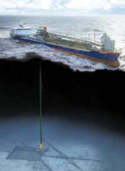
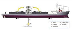
The most efficient way to install the rock corridor for a pipeline at any pockmark location is the use of a flexible fall pipe vessel (FFPV). An FFPV is a dedicated vessel for the accurate installation of gravel and rock in deeper water. The vessels also are used frequently for gravel and rock placement to prevent upheaval buckling, protect flowlines and umbilicals, avoid excessive free spanning of pipelines, ensure acceptable separation between crossing pipelines, and for a host of subsea intervention work in both pre-lay and post-lay phases.
Van Oord’s FFPVs,Nordnes and Stornes, can work at dumping depths of 1,200 m (3,936 ft). Jan De Nul launched a FFPV named Simon Stevin in March 2009 with a maximum discharge depth of 2,000 m (6,561 ft) and a rock carrying capacity of 33,500 metric tons (36,927 tons). The maximum operational depth for Boskalis’ Seahorse FFPV is 1,500 m (4,921 ft). Tideway’s FFPV Flintstone, with a speed of 15 knots, has a loading capacity of 19,000 metric tons (20,943 tons) and reportedly can place rocks accurately up to a water depth of 2,000 m (6,561 ft).
Project application
A recent example of deepwater rock installation is the Ormen Lange southern field extension project in Norway. The seabed location of the field is on top of a prehistoric slide area which left the seabed extremely uneven with undulations of every scale. Van Oord was awarded the rock installation contract for this project where the work entailed installation of rocks for support and protection of pipelines and umbilicals extending from shore at Nyhamna to the field development area. The works entailed both pre-lay and post-lay rock installation at maximum depths of 870 m using 2.8 million metric tons (3.08 million tons) of rock. VOO used its FFPVsNordnes and Tertnes to execute the work between 2004 and 2007. Another example of rock placement is that of Boskalis using two vessels, Sandpiper and Seahorse, to perform gravel dumping for pre- and post-lay stage work at the Gullfaks satellites project in Norway. The project is in 135 m (443 ft) of water.
In February 2009, Tideway’sRollingstone placed 20,000 cu m (706,293 cu ft) of rock at a depth of 987 m (3,238 ft) as part of its subsea intervention contract work for the Enagas Balearic Pipeline project in the Mediterranean Sea. In January 2009, Boskalis was awarded a contract in joint venture with Tideway to place about 320,000 metric tons (352,739 tons) of rock to level and stabilize the seabed along the full distance of the Nord Stream pipeline in the Baltic Sea. More recently, in April 2010, the Boskalis-Tideway JV acquired a letter of intent to install rock berms after the Nord Stream pipeline is laid.
Uneven seabeds
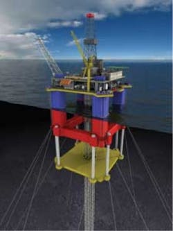
Slopes due to uneven seabed are not unusual. Such conditions sometimes are caused by boulders and gravels or relatively soft seabed material. This might create an array of problems such as exceeding the allowable free span of a pipeline; sudden transitions into steeper slopes resulting in difficulty laying pipe; uneven foundation/base for a subsea structure; or misalignment between a jumper and a connector attached to a subsea structure such as a PLET/PLEM already on the seabed. One solution to these problems is to prepare an acceptably flat seabed for the pipeline or the subsea structure, as the case may be. Such pre-lay preparation of a deep seabed may require trenching, leveling, and/or construction of rock beds and berms using large volumes of rock to level and stabilize the seabed.
Challenges
Excavation in deep water faces a number of challenges, including:
- Equipment alternatives available – Deeper seabeds are not accessible using conventional hydraulic excavation tools
- Deployment – The water depth requires very long cables and hoses which are difficult to handle
- Positioning – The usual method of positioning the vessel to control excavator position is unreliable at deeper seawater depths
- Survey – A precise survey before, during, and after excavation is imperative for the success of the project.
Applicable equipment
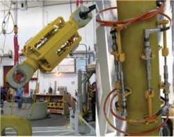
AGR Subsea Ltd (AGR) of Aberdeen, UK, is one of few contractors experienced in deepwater excavation and seabed flattening jobs. Typically, AGR uses two types of equipment – the SeaVator range (including AquaDrive and PropDrive tools) for soils with undrained shear strength capacity of up to 50 kPa and the ClayCutter X for soils ranging from 50 to 500 kPa. SeaVator tools and analogues have been used regularly since the mid 1990s on excavation, trenching, and flattening jobs in soft clays. ClayCutter X was used at the Ormen Lange in Norway in summer 2008 to trench and flatten tough clays of up to 400 kPa shear strength at an average of 870 m (2,854 ft) water depth.
The SeaVator uses the mass flow excavation (MFE) principle to drive a dedicated column of water towards the seabed in order to alter the seabed regime by dispersing loose cover and soft clays. The SeaVator does not contact the seabed, pipeline, or installation. For tougher soils and faster trenching, a jet system is used in tandem with the SeaVator. This allows trenching to a maximum depth of 5 m (16.4 ft). The jetting impact is created by a high-pressure pump with a rated capacity of 3,000 hp at 2,000 rpm.
ClayCutter X can create a 5-m (16.4-ft) wide trench in soils with undrained shear strength up to 400 kPa, and is claimed to be capable of working in unlimited water depths.
AGR Subsea equipment is deployed typically from a dynamically positioned heavy duty FFPV equipped with an ROV and a dedicated survey crew. The use of the ROV allows the SeaVator to be positioned accurately even in deepwater, and offers a stable survey platform.

Another innovative dredging system called “Spider” has been developed by Nexans, a Paris-based company, in association with Norwegian company GTO and other specialized vendors and suppliers. Spider is based on merging the Capjet trenching system with the undercarriage of a Swiss timber vehicle to achieve maximum terrain capacity. It uses water jetting at up to 1,960 kPa (284 psi) pressure to fluidize the seabed followed by a suction system to remove large volumes of soil and can be controlled with 10-20 cm (3.9-7.9 in.) precision, even at a depth of 1,000 m (3,280 ft).
The movement of the vehicle is controlled by operators on a support vessel through a specific launch and recovery system (LARS). An umbilical interconnects the vessel to the Spider to provide necessary power and signals. At the beginning of the operations, operators can follow Spider’s movements using underwater cameras. However, as stirred up material reduces visibility, the Spider is controlled by a combination of 3D software, sensors mounted on all movable parts of the machine, and a network of acoustic transmitters placed on the ocean floor. The 3D model of the seabed is updated continuously using a human-machine interface (HMI) to show the terrain changes.
Project application
The Ormen Lange southern field extension project in Norway is an example where extensive deepwater excavation and seabed flattening have been done. On this project, the uneven seabed rendered the installation of pipelines impossible because of excessive free-spans and point loads. To install pipelines between the various drill centers and back to shore, a combination of seabed excavation and a rock dump program was devised. The significant challenges faced by the contractor were as follows:
- Seawater depth of 870 m
- Uneven conditions with the seabed being constituted of boulders, gravels, sands, and clays with undrained shear strength of up to 500 kPa (10 kpsf)
- Unpredictable metocean conditions.
The scope of work included excavating a number of 5 m (16 ft) wide trenches in seabed during the pre-pipelay phase and leveling certain areas of seabed prior to template installation. AGR used Claycutter X and high-pressure pumps in addition to Seavator equipment to successfully complete the operation within 18 days.
In June 2010, AGR reported it has been retained to provide excavation services on the Gorgon project offshore Western Australia. Work here will entail cutting a trench on a steep scarp shoulder to reduce the height and length of the free span along the pipeline route.
The first Spider was constructed and tested in the Ormen Lange in 2004. Thereafter, Spiders were used to dredge at the edge and at the upper parts of slopes up to 30o steep before laying the offshore pipeline. Maximum day-rate per Spider was approximately 100 cu m (3,531 cu ft) and the maximum depth of trench excavated was 4 m (13.1 ft).
Conclusion
Integration of innovative practices and technologies into new vessels has enabled offshore operators and contractors to successfully lay pipelines and subsea structures in challenging environments.
Since necessity is the mother of invention, it is expected that in the coming years, further incorporation of novel equipment will allow operators and contractors to move into new frontiers in offshore oil and gas extraction. As these technologies are developed and deployed, oil and gas companies will be able to turn their attention to new fields offshore Brazil, in the deepwater Gulf of Mexico, off the Alaskan coast, and in the Norwegian Sea – areas where irregular seabed conditions have stymied development in the past.
Offshore Articles Archives
View Oil and Gas Articles on PennEnergy.com